
Self-adaptive focused ultrasonic treatment head

A focused ultrasound, self-adaptive technology, applied in the direction of ultrasound therapy, treatment, etc., can solve problems such as faults, increased focused ultrasound treatment head and human body, and the inability of ultrasonic transmission to achieve wide application range, simple structure, component maintenance and replacement convenient effect

Pending Publication Date: 2020-01-21
南京光声超构材料研究院有限公司
View PDF0 Cites 9 Cited by
  • Summary
  • Abstract
  • Description
  • Claims
  • Application Information

AI Technical Summary

Problems solved by technology

This focused treatment head has two obvious disadvantages: First, for lesions with different depths in the human body, it is necessary to adjust the distance between the focused ultrasound treatment head and the human body
When the lesion is shallow, it is necessary to increase the distance between the focused ultrasound treatment head and the human body, which may cause the separation of the ultrasonic coupling agent water bag of the focused ultrasound treatment head from the skin of the human body, resulting in the inability of the ultrasound to effectively transmit to the lesion.
When the lesion is deep, it is necessary to reduce the distance between the focused ultrasound treatment head and the human body, which may also cause excessive pressure on the ultrasonic coupling agent water bag of the focused ultrasound treatment head, resulting in structural damage to the transducer inside the treatment head or Fault
Second, this kind of focusing transducer does not integrate related imaging equipment (such as B-ultrasound probe), so it is not conducive to the simultaneous monitoring of ultrasound treatment process in clinical

Method used


Image

  • Self-adaptive focused ultrasonic treatment head

Examples


Embodiment Construction

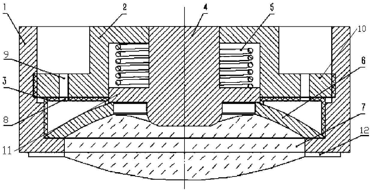
[0017] like figure 1 As shown, an adaptive focusing ultrasonic treatment head includes a shell 1, a fixed cover 2, a probe 4 and a hollow focusing transducer 6, and the fixed cover 2, the probe 4 and the hollow focusing transducer 6 are all arranged inside the shell 1 , the outer wall of the bottom of the fixed cover 2 is provided with a first boss 10, the outer wall of the first boss 10 is provided with an external thread, the inner wall of the housing 1 is provided with an internal thread matching the external thread, and the probe 4 is located on the fixed Inside the cover 2, the hollow focusing transducer 6 is arranged under the fixed cover 2, and the middle part of the hollow focusing transducer 6 is provided with a first through hole in the vertical direction, and the probe 4 penetrates through the first through hole and is arranged in the hollow focusing Inside the transducer 6, the outer wall of the probe 4 is provided with a second boss 11, the lower surface of the se...


PUM


Abstract

The invention provides a self-adaptive focused ultrasonic treatment head, and relates to the technical field of ultrasonic equipment. The self-adaptive focused ultrasonic treatment head comprises a shell, a fixed cover, a probe and a hollow focused transducer. A first boss is arranged on the outer side wall of the bottom of the fixed cover, an external thread is arranged on the outer side wall ofthe first boss, an internal thread matched with the external thread is arranged on the inner side wall of the shell, a first through hole is formed in the middle part of the hollow focused transducerin the vertical direction, the probe penetrates through the first through hole and is arranged in the hollow focused transducer, a second boss is arranged on the outer side wall of the probe, the lower surface of the second boss is connected with the upper surface of the hollow focused transducer in a clamping mode, a spring sleeves the outer side wall of the probe, an ultrasonic coupling agent water bag is arranged at the bottom part of the hollow focused transducer, a frame is arranged on the outer side wall of the ultrasonic coupling agent water bag, and a bolt penetrates through a second through hole and a threaded groove to connect the frame and the shell. The self-adaptive focused ultrasonic treatment head has a wider application range, is simple in structure and can realize synchronous monitoring.

Description

technical field [0001] The invention belongs to the technical field of ultrasonic equipment, and in particular relates to an adaptive focusing ultrasonic treatment head. Background technique [0002] Ultrasound therapy, as a non-invasive and efficient treatment method, has been widely used in the medical field. Among them, focused ultrasound is a treatment technique that can focus the ultrasound beam to a smaller area (focal area) to generate heat for the lesion tissue to ablate it without damaging the surrounding tissue. Since the effective working focal area of ​​focused ultrasound therapy is often small, it is necessary to adjust the distance between the focused ultrasound treatment head and the human body according to the depth and depth of different lesions in clinical treatment. Cooperate with the appropriate size couplant device. This brings a lot of inconvenience in clinical use, and also greatly limits the treatment of different patients or lesions with different ...

Claims


Application Information

Patent Timeline
Patent Type & Authority Applications(China)
IPC IPC(8): A61N7/02
CPCA61N7/02A61N2007/0086
Inventor 钱登林颜学俊耿开胜钱斯文
Owner 南京光声超构材料研究院有限公司
Learn More