
Anti-collision double-head laser cutting and marking integrated machine.

A laser cutting and anti-collision technology, which is applied in laser welding equipment, manufacturing tools, metal processing equipment, etc., can solve problems such as low production efficiency, unfavorable long-term use of laser cutting and marking all-in-one machines, cable collision, and winding, etc., to achieve The effect of avoiding the hidden danger of collision or winding

Active Publication Date: 2020-01-21
安徽同兴科技发展有限责任公司
View PDF6 Cites 0 Cited by
  • Summary
  • Abstract
  • Description
  • Claims
  • Application Information

AI Technical Summary

Problems solved by technology

[0002] The laser cutting machine uses laser to cut the workpiece into the target shape, while the laser marking machine uses laser to engrave and mill the target pattern or text within a certain working range. Due to the dual requirements of marking workpieces, if the laser cutting head and laser marking head are simply installed on the same mechanical frame, the cables of the double laser heads will inevitably collide and entangle on similar travel paths, which is not conducive to the integration of laser cutting and marking. The long-term use of the machine, and the traditional way of marking first and then cutting is low in production efficiency

Method used


Image

  • Anti-collision double-head laser cutting and marking integrated machine.
  • Anti-collision double-head laser cutting and marking integrated machine.
  • Anti-collision double-head laser cutting and marking integrated machine.

Examples


Embodiment Construction

[0010] In order to make the purpose, technical solutions and advantages of the embodiments of the present invention clearer, the technical solutions in the embodiments of the present invention will be clearly and completely described below in conjunction with the drawings in the embodiments of the present invention. Obviously, the described embodiments It is a part of embodiments of the present invention, but not all embodiments. Based on the embodiments of the present invention, all other embodiments obtained by persons of ordinary skill in the art without creative efforts fall within the protection scope of the present invention.

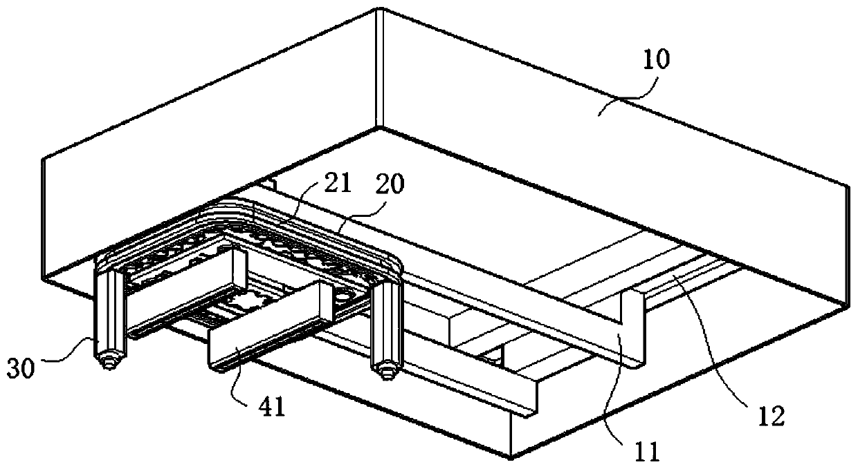
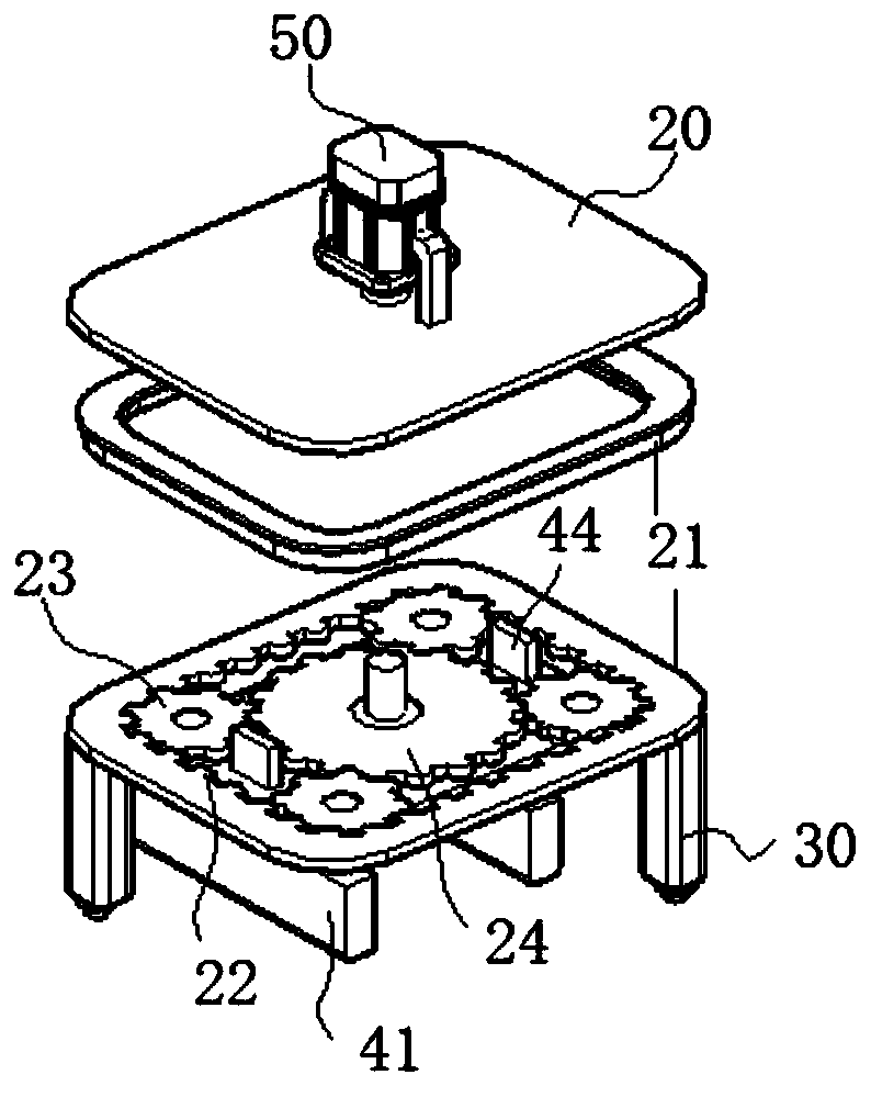
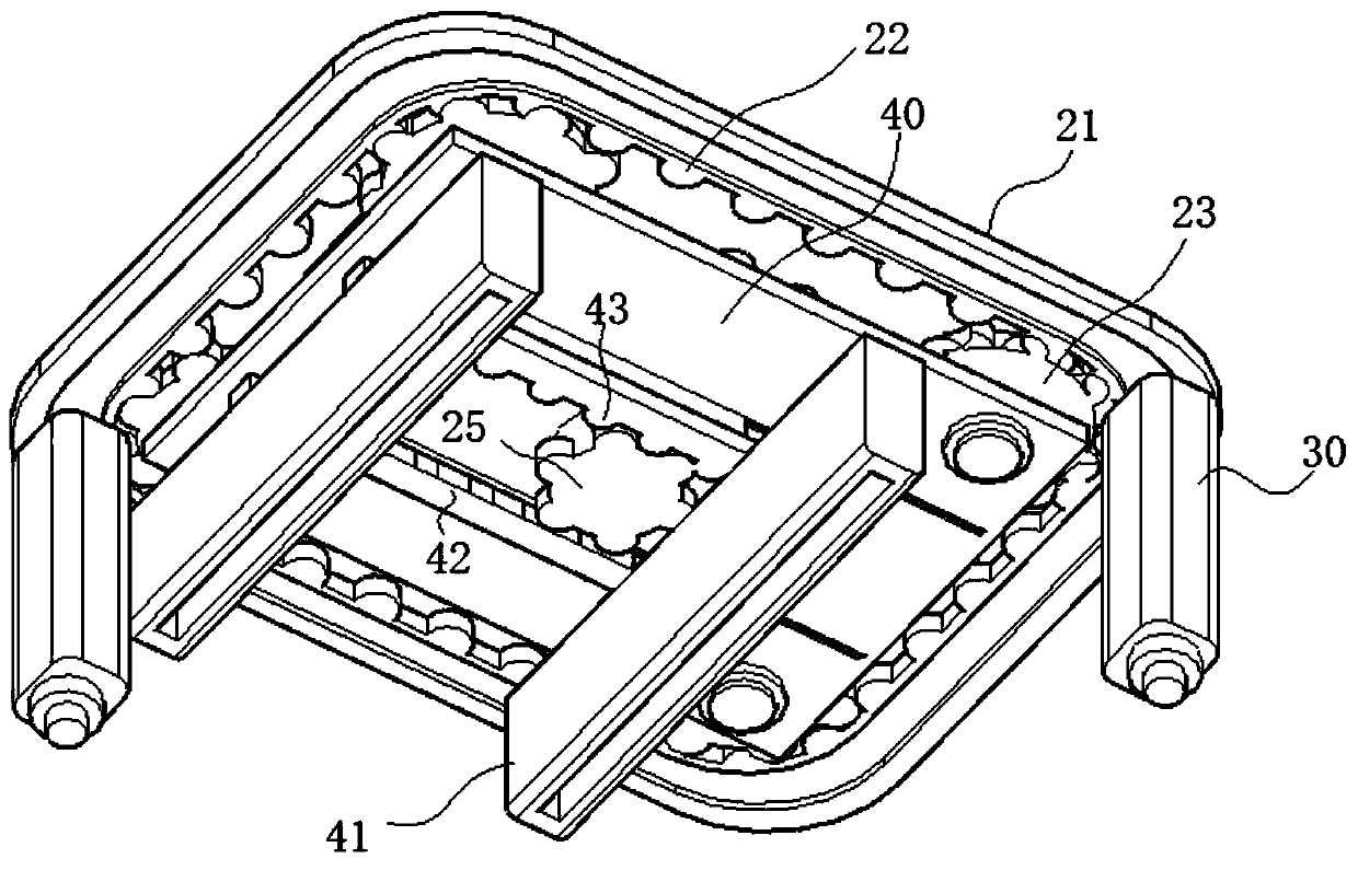
[0011] see Figure 1-4 As shown, an anti-collision duplex head laser cutting and marking all-in-one machine includes a top shell 10 provided with horizontal guide rails 11 and longitudinal guide rails 12 that intersect horizontally and vertically in a well-shaped shape and are slidably connected. The foreman seat 20, the top of the transverse gui...


PUM


Abstract

The invention relates to the field of laser marking machine equipment, and discloses an anti-collision double-head laser cutting and marking integrated machine. The anti-collision double-head laser cutting and marking integrated machine comprises a machine top housing provided with a transverse guide rail and a longitudinal guide rail, wherein the bottom end of the transverse guide rail is slidably connected with a head seat; the bottom end of the head seat is slidably connected with a suspension belt along an edge line; two cutting heads are suspended at the bottom end of the suspension belt;a bottom plate is connected below the head seat; a second gear is arranged at the top end of the bottom plate; a rotary driver for driving the second gear to rotate is arranged at the bottom end of the head seat; the suspension belt is in meshed transmission with the second gear through a transmission piece; a gear shaft of the second gear penetrates through the bottom plate and is provided witha third gear; the bottom end of the bottom plate is slidably connected with two marking heads which are arranged at an interval; and the top ends of the two marking heads are engaged with the third gear. According to the anti-collision double-head laser cutting and marking integrated machine, the marking heads slide and mark within a certain range of a workpiece, and meanwhile, the cutting heads cut the workpiece around a marking area, so that marking and cutting are synchronously carried out, and the hidden danger of collision or winding caused by intersection of walking paths is avoided.

Description

technical field [0001] The invention relates to the field of laser marking machine equipment, in particular to an anti-collision duplex head laser cutting and marking integrated machine. Background technique [0002] The laser cutting machine uses laser to cut the workpiece into the target shape, while the laser marking machine uses laser to engrave and mill the target pattern or text within a certain working range. Due to the dual requirements of marking workpieces, if the laser cutting head and laser marking head are simply installed on the same mechanical frame, the cables of the double laser heads will inevitably collide and entangle on similar travel paths, which is not conducive to the integration of laser cutting and marking. The long-term use of the machine, and the traditional production efficiency of marking first and then cutting is low. Contents of the invention [0003] Aiming at the deficiencies of the prior art, the present invention provides a laser cuttin...

Claims


Application Information

Patent Timeline
Patent Type & Authority Applications(China)
IPC IPC(8): B23K26/362B23K26/38B23K26/70
CPCB23K26/362B23K26/38B23K26/702
Inventor 罗群罗亮
Owner 安徽同兴科技发展有限责任公司
Learn More