Flexible lifting appliance

A spreader and hoisting technology, applied in the direction of load hoisting components, transportation and packaging, can solve the problems such as the difficulty of clamping and transporting the opening parts, and achieve the effects of improving quality and safety risks, wide application and simple use.

Pending Publication Date: 2020-01-21
XINXING HEAVY IND HUBEI 3611 MECHANICAL
View PDF0 Cites 1 Cited by
  • Summary
  • Abstract
  • Description
  • Claims
  • Application Information

AI Technical Summary

Problems solved by technology

[0003] The purpose of the present invention is to provide a flexible lifting device for convenient and fast clamping for a kind of situation that the parts with notches are not easy to be clamped and transported, so that the hoisting and transporting are more convenient

Method used


Image

  • Flexible lifting appliance
  • Flexible lifting appliance
  • Flexible lifting appliance

Examples


Embodiment Construction

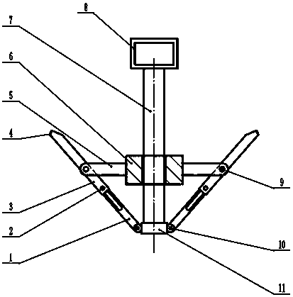
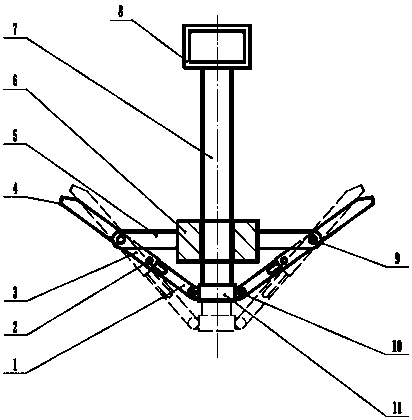
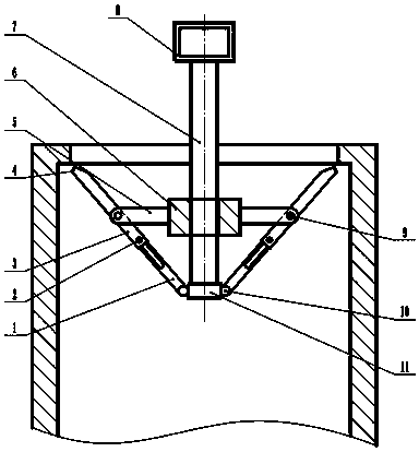
[0019] figure 1 Among them, the present invention consists of a telescopic rod, a support rod 5, a sliding sleeve 6, a hoisting main rod 7 and a hoisting ring 9. The telescopic rod is composed of a telescopic rod proximal component 1, a telescopic rod pin 2, a telescopic rod distal component 3, and a telescopic rod. The end assembly 4 is composed.

[0020] The hoisting ring 8 is hung on the crane hook, the hoisting main pole 7 is fixedly connected to the hoisting main pole, and the hoisting main pole end stop assembly 11 is fixed to the issuing end of the hoisting main pole 7.

[0021] The sliding sleeve 6 is sleeved on the hoisting main pole 7, and can slide freely on the hoisting main pole 7. The sliding sleeve 6 is fixed with 3 or more support poles 5, and the sliding sleeve 6 drives the supporting pole 5 along the hoisting main pole 7 Swipe up and down.

[0022] The outermost end of each support rod 5 and the hole on the middle side of the telescopic rod distal assembly 3 are co...


PUM


Abstract

The invention relates to a flexible lifting appliance which comprises a lifting main rod, a sliding sleeve slidably sleeving the lifting main rod, and a telescopic rod assembly. The telescopic rod assembly comprises multiple telescopic rods; each telescopic rod comprises a telescopic rod far-end assembly and a telescopic rod near-end assembly connected in a sleeving way; the telescopic rod far-endassemblies are movably arranged in waist-shaped holes in the telescopic rod near-end assemblies through telescopic rod pins; the middle parts of the telescopic rod far-end assemblies are hinged withmultiple support rods arranged outside the sliding sleeve in a surrounding way; the lower ends of the telescopic rod near-end assemblies are hinged to a lifting main rod stop end assembly at the lowerend of the lifting main rod; a lifting ring is arranged at the upper end of the lifting main rod; the upper ends of the telescopic rod far-end assemblies are clamping parts adaptive to a seam allowance of a component to be lifted; and the clamping parts comprise plane parts adaptive to the lower end face of the seam allowance of the component to be lifted, and side face parts connected with the plane parts and adaptive to the inner wall face of the seam allowance of the component to be lifted. The flexible lifting appliance provided by the invention is easy to manufacture, convenient to use,simple in structure, low in cost, easy to maintain, and wide in applicability.

Description

Technical field [0001] The invention belongs to the hoisting equipment for stop / pipe parts. Background technique [0002] When processing some parts with stop / nozzle (such as flywheel housing, pump housing, etc.), the parts need to be hoisted to the equipment platform first. The usual method is to use a sling to pass through the stop of the entire part Hoist, hoist to the machine platform to remove the sling rope, and clamp the parts while laying flat. This can easily cause the parts to fall when the sling is removed, causing quality and safety issues, and the entire assembly and unloading takes a long time, which affects production efficiency. Summary of the invention [0003] The purpose of the present invention is to provide a flexible spreader that is convenient and fast to be clamped in view of the situation that a kind of spigot parts are not easy to be clamped and transported, so that the hoisting and transporting is more convenient. [0004] The technical solution of the p...

Claims


Application Information

Patent Timeline
Patent Type & Authority Applications(China)
IPC IPC(8): B66C1/56
CPCB66C1/56
Inventor 饶鑫宇葛汉武
Owner XINXING HEAVY IND HUBEI 3611 MECHANICAL
Why Eureka
Try Eureka