
Semi-automatic chemical raw material barrel transfer vehicle structure

A technology for chemical raw materials and transfer vehicles, which is applied to motor vehicles, trolleys, trolley accessories, etc., can solve the problems of limited use process convenience, cumbersome operation of raw material barrels, and large volume of external equipment, and achieves stable lifting and convenient unloading. , the effect of improving safety

Active Publication Date: 2021-07-13
XUZHOU COLLEGE OF INDAL TECH
View PDF6 Cites 4 Cited by
  • Summary
  • Abstract
  • Description
  • Claims
  • Application Information

AI Technical Summary

Problems solved by technology

[0003] However, these external devices are bulky and have limited convenience during use, and the use of forklifts and other tools still requires manual lifting of one end of the raw material barrel to facilitate the forklift or trailer to load the raw material barrel. The supporting bracket of the forklift is cumbersome to operate when unloading the raw material barrels; at present, forklifts and other equipment generally need to be driven by electricity, and most of the chemical raw materials are flammable and explosive, even if equipped with explosion-proof motors, there are still some problems. security risks

Method used


Image

  • Semi-automatic chemical raw material barrel transfer vehicle structure
  • Semi-automatic chemical raw material barrel transfer vehicle structure
  • Semi-automatic chemical raw material barrel transfer vehicle structure

Examples


Embodiment 1

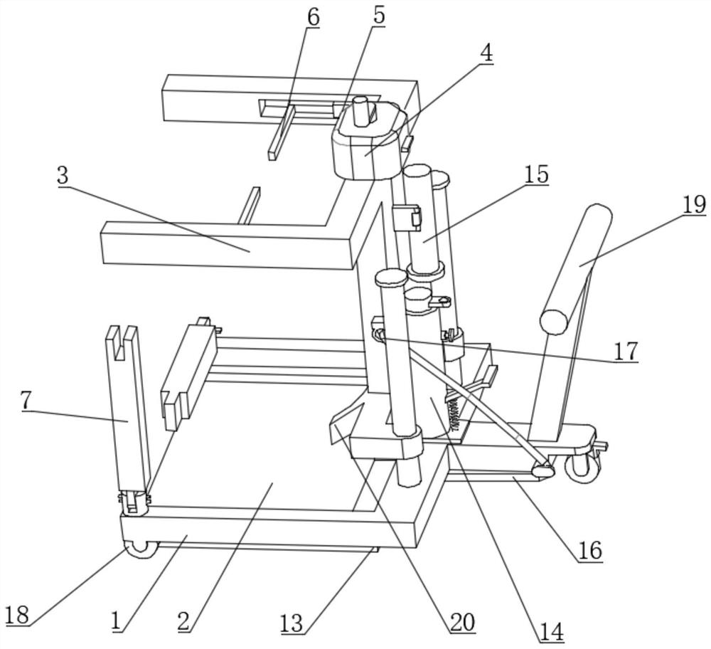
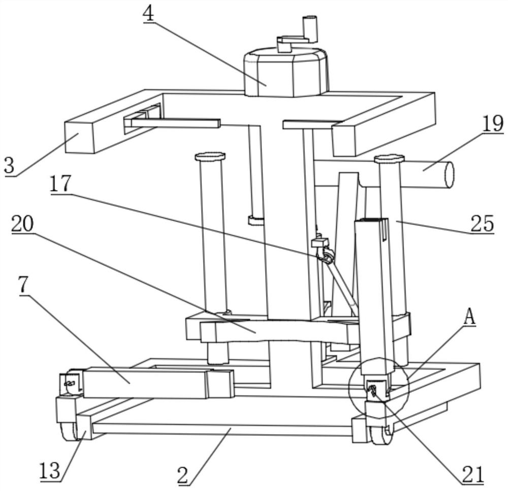
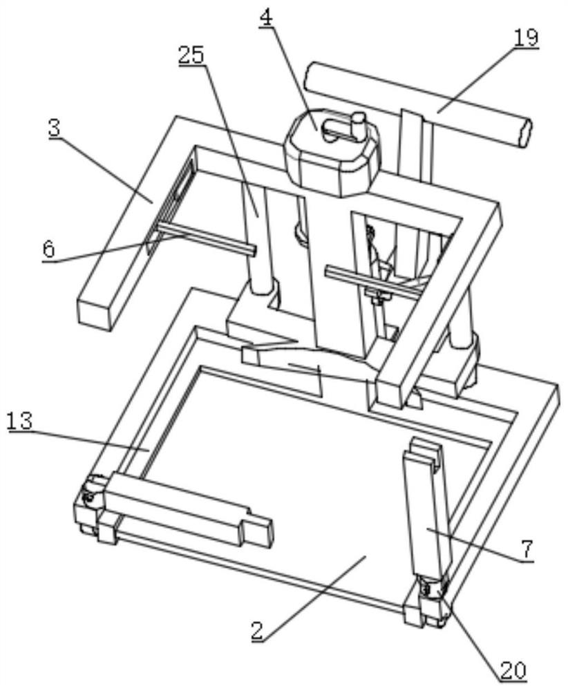
[0037] Embodiment 1. The crosspiece mechanism includes a hand pump 4, and the hand pump 4 communicates with two telescopic cylinders 5. The telescopic end of the telescopic cylinder 5 is connected with a gear lever 6, and the gear lever 6 is connected to the fork. The frame 3 is slidingly connected, and by manually shaking the hand pump 4, the two telescopic cylinders 5 can drive the gear rod 6 to move to the left, that is, to pry the upper end of the raw material barrel, so that a space appears below the raw material barrel,

[0038] For this embodiment, in order to keep the raw material barrel stable when the gear rod 6 pushes the raw material barrel, the two sides of the upper end surface of the frame 1 are respectively provided with limit rods 7, such as figure 2 As shown, the frame 1 is respectively hinged to two limit rods 7 through a cylinder 21, and the ends of the two limit rods 7 are respectively presented as image 3 grooves and projections, so as to realize snap-f...

Embodiment 2

[0040] Embodiment 2, in order to reduce the volume and increase the adaptability of the whole structure to meet the application of larger raw material barrels, the crosspiece mechanism adopts the form of a steel wire rope 8, and specifically the upper end surface of the fork frame 3 is U-shaped, and The closed end of the U-shape is provided with a control cavity 9, and a rotating shaft 10 is rotatably connected to the control cavity 9. The two ends of the steel wire rope 8 bypass the open end of the U-shape and extend into the control cavity 9 and are fixed with the rotating shaft 10. connection, when used as Figure 12 In the shown state, the bottom plate 2 is on one side to prevent from obstructing the raw material bucket, and the steel wire rope 8 is in a state of tension and straightness. Then the fork frame 3 will be driven by pushing the push handle 19 close to the raw material bucket as Figure 12 As shown, in the process of approaching, because the steel wire rope 8 i...


PUM


Abstract

The invention discloses a semi-automatic chemical raw material barrel transfer vehicle structure which comprises a frame serving as a bearing foundation, wheels located at the bottom of the frame and a movably-arranged bottom plate, a fork frame is connected to the frame, and a crosspiece mechanism is arranged on the fork frame. The crosspiece mechanism tilts one end of the raw material barrel through displacement, so that the bottom of the raw material barrel and the ground form a space capable of being plugged into the bottom plate, and the raw material barrel is transferred to the bottom plate through displacement change of the crosspiece mechanism. The structure does not contain electric power equipment and does not generate electric sparks, and can adapt to a safety anti-explosion requirement in a chemical production site. In a steel wire rope mode, a buffer spring can be arranged to make contact with the side wall of the raw material barrel in a larger attaching area, a shell of the raw material barrel can be protected, the inclination situation is not prone to occurring, in addition, the length of the steel wire rope can be controllably changed, the tilted raw material barrel can be conveniently put down, and the steel wire rope can be used as a lasso and can be kept stable in the advancing process.

Description

technical field [0001] The invention relates to the technical field of chemical equipment and supplies, in particular to a semi-automatic transfer car structure for chemical raw material barrels. Background technique [0002] Chemical raw material barrels are common containers used to hold liquids in chemical production. At present, most raw material barrels are heavy after being filled with materials. It is difficult to rely on manual labor when temporary transfer is required. At present, most of the handling All need external tools and equipment, such as forklifts, trailers, etc. [0003] However, these external devices are large in size, and the convenience of use is limited, and the use of tools such as forklifts still needs to manually lift one end of the raw material barrel to facilitate the forklift or trailer to load the raw material barrel. The supporting bracket of the forklift is cumbersome to operate when unloading the raw material barrel; at present, forklifts ...

Claims


Application Information

Patent Timeline
IPC IPC(8): B62B3/04B62B3/065B62B5/00
CPCB62B3/0618B62B2202/028B62B3/06B62B5/00Y02W90/10
Inventor 李想吴祥林李兵李敢刘广勇
Owner XUZHOU COLLEGE OF INDAL TECH
Learn More