Beam bottom formwork detaching mechanism and beam bottom formwork detaching method

The technology of bottom formwork and steel formwork is applied in the field of beam bottom formwork dismantling mechanism, which can solve problems such as poor construction quality, and achieve the effects of fast construction speed, improvement of removal efficiency and labor saving.

Active Publication Date: 2020-01-21
CHINA FIRST METALLURGICAL GROUP
View PDF6 Cites 2 Cited by
  • Summary
  • Abstract
  • Description
  • Claims
  • Application Information

AI Technical Summary

Problems solved by technology

[0003] One of the purposes of this application is to provide a beam bottom formwork removal mechanism and a beam bottom formwork removal method, aiming to improve the poor construction quality of the existing foundation pit support system

Method used


Image

  • Beam bottom formwork detaching mechanism and beam bottom formwork detaching method
  • Beam bottom formwork detaching mechanism and beam bottom formwork detaching method
  • Beam bottom formwork detaching mechanism and beam bottom formwork detaching method

Examples


Embodiment

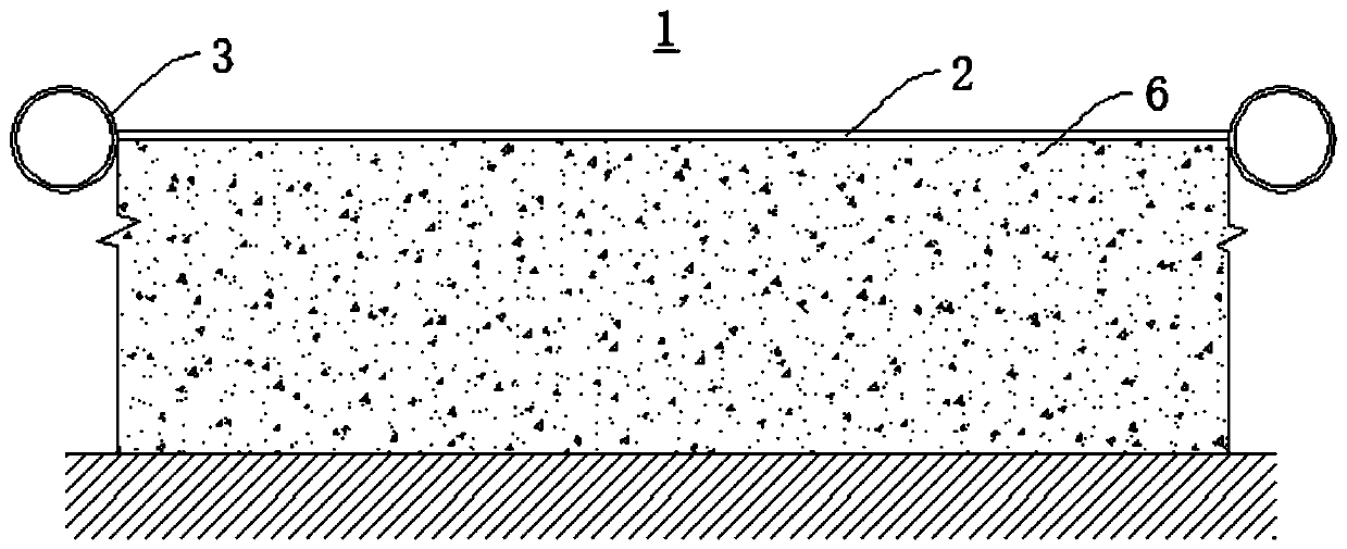
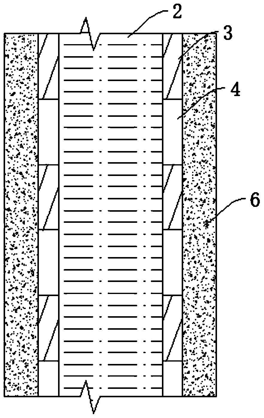
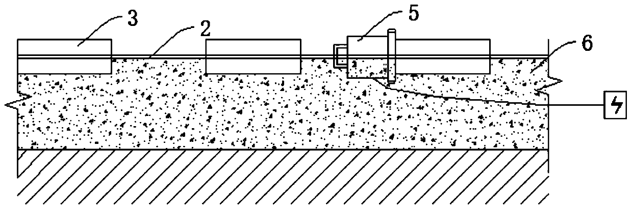
[0037] Please refer to figure 1 , with reference to figure 2 and image 3 , the present application provides a beam bottom formwork removal mechanism 1, which includes a beam lower steel formwork 2 arranged on a concrete cushion 6, a plurality of vibration steel sleeves 3 and a plurality of vibration assemblies 5, and the opposite two sides of the beam lower steel formwork 2 A plurality of vibrating steel sleeves 3 arranged at intervals are respectively installed on the sides, and there is a static space 4 between adjacent vibrating steel sleeves 3; The connection is vibrated correspondingly, so that the concrete cushion 6 near the position of the steel formwork 2 under the beam falls off and is removed.

[0038] It should be noted that, in this embodiment, a plurality of vibrating steel sleeves 3 are sequentially arranged at intervals along the length direction of the steel formwork 2 under the beam.

[0039]It should be noted that, in this embodiment, the intervals betwe...


PUM


Abstract

The invention provides a beam bottom formwork detaching mechanism and a beam bottom formwork detaching method, and belongs to the field of building construction. The beam bottom formwork detaching mechanism comprises an under-beam steel formwork, a plurality of vibration steel sleeves and a plurality of vibration assemblies, wherein the under-beam steel formwork is arranged on a concrete base layer, the vibration steel sleeves are arranged on the two opposite lateral sides of the under-beam steel formwork at intervals, standing spaces are formed between every two adjacent vibration steel sleeves, and the vibration assemblies are connected with the vibration steel sleeves in a vibration mode so that the concrete base layer close to the under-beam steel formwork can fall off to be removed. The beam bottom formwork detaching mechanism is reasonable in structure, convenient to use, convenient to detach and high in safety performance and saves manpower and materials.

Description

technical field [0001] The application relates to the field of building construction, in particular to a beam bottom formwork removal mechanism and a beam bottom formwork removal method. Background technique [0002] In recent years, with the rapid development of cities, the safety requirements of modern engineering construction technology are getting higher and higher, especially the support system of deep foundation pits in foundation engineering. The general construction method is to put a layer of plastic film on the cushion before pouring the supporting beams. When the film is damaged in the later stage, some cushions and beams will be firmly bonded, which will have a major impact on the subsequent foundation pit construction. Security risks. And the current construction method of removing the cushion layer is to use the mechanical arm of the excavator to forcibly strike the cushion layer to cause it to fall off. Continuous knocking and impact loads lead to stress fati...

Claims


Application Information

Patent Timeline
Patent Type & Authority Applications(China)
IPC IPC(8): E04G19/00E02D17/04
CPCE02D17/04E02D2250/0007E04G19/00
Inventor 王艳龙喻程徐攀夏杰龚俊
Owner CHINA FIRST METALLURGICAL GROUP
Why Eureka
Try Eureka