Display screen module and electronic equipment
A display module and electronic equipment technology, applied in TVs, electrical components, static indicators, etc., can solve problems that affect the display of user interface content, fail to realize full screen, and destroy screen integrity, etc., to improve user experience, Good display effect, reduced design cost and hardware cost
- Summary
- Abstract
- Description
- Claims
- Application Information
AI Technical Summary
Problems solved by technology
Method used
Image

Examples
Embodiment 1
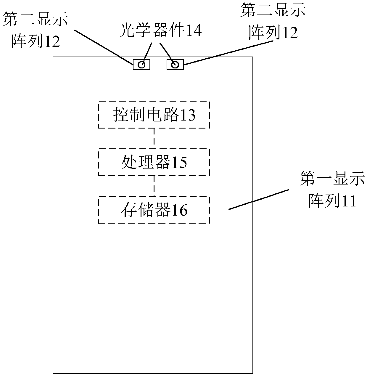
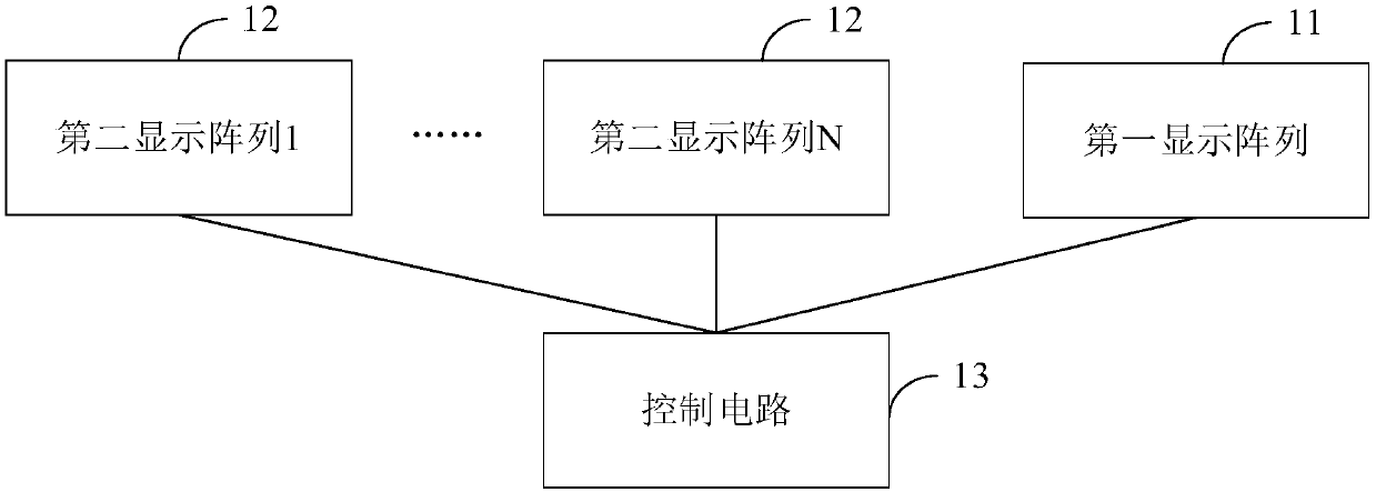
[0051] see figure 2 , image 3 , this embodiment discloses a display screen module, which can be applied to various electronic devices mentioned above. The display screen module includes: a first display array 11, one or more second display arrays 12, and a control circuit 13.
[0052] In this embodiment, the bottom of one or more second display arrays includes one or more groups of optical devices 14 (that is, the optical devices are below the display screen of electronic equipment that we usually see), and each group of optical devices includes at least An optical device, where the optical device is a component that requires ambient light to operate. For example, a set of optics may include only the front camera, or may include both the front camera and other sensors such as ambient light sensors or proximity light sensors that require ambient light to function.
[0053] In this application, the basic unit of the display array is each pixel used for display (such as a li...
Embodiment 2
[0069] Based on the above embodiments, this embodiment will describe in detail the implementation of the control circuit 13 when the first display array is the AMOLED array 11 and the second display array is the PMOLED array 12 .
[0070] One of the implementation methods is to design a circuit for the AM array and the PM array, and the circuit designs independent pins for the rows and columns of the AM array and the PM array, so as to realize the control of the AM array and the PM array. In the prior art, the control circuit used to control the display array (such as AM array) usually includes a driver IC chip. If it is necessary to add pins for controlling the PM array, the existing driver IC for the AM array needs to be redesigned. Chip, so that it can be added to the pin for controlling the PM array, or independently design a driver IC chip for controlling the PM array. Either way will increase the cost (including design cost and hardware cost), and at the same time, it wi...
Embodiment 3
[0079] Based on the second embodiment, this embodiment discloses a display module, see Image 6 , the display module also includes: a plurality of PMOLED drivers 14 on the basis of the second embodiment, each PMOLED driver 14 in the plurality of PMOLED drivers is respectively connected to a data pin 132 in some data pins and one or A column in multiple PMOLED arrays is connected;
[0080] When the driving circuit is used to drive one or more PMOLED arrays through part of the data pins, it is specifically used to drive one or more PMOLED arrays through part of the data pins and the PMOLED driver.
[0081] In this embodiment, the driver is a device used to drive the PM. Since the PM pixel needs a relatively large current when it is lit (that is, "driven"), and the current that the existing driving circuit can generate is relatively small, Therefore, a driver needs to be added so that it can drive the pixels in the PM array. The realization of the driver is an existing technolo...
PUM
 Abstract
Description
Claims
Application Information
 - R&D
- Intellectual Property
- Life Sciences
- Materials
- Tech Scout
- Unparalleled Data Quality
- Higher Quality Content
- 60% Fewer Hallucinations
Browse by: Latest US Patents, China's latest patents, Technical Efficacy Thesaurus, Application Domain, Technology Topic, Popular Technical Reports.
© 2025 PatSnap. All rights reserved.Legal|Privacy policy|Modern Slavery Act Transparency Statement|Sitemap|About US| Contact US: help@patsnap.com