Photoelectric composite cable

A photoelectric composite cable and cable core technology, applied in the direction of insulated cables, cable/conductor manufacturing, conductor/cable insulation, etc., can solve the problems such as the structural unit is not easy to slip, the structure is not round, the weight of the optical cable is large, etc., to meet the requirements Anti-rodent performance, satisfying environmental performance, effect satisfying anti-termite performance

Active Publication Date: 2020-01-21
INST OF HIGH ENERGY PHYSICS CHINESE ACAD OF SCI +1
View PDF11 Cites 0 Cited by
  • Summary
  • Abstract
  • Description
  • Claims
  • Application Information

AI Technical Summary

Problems solved by technology

[0002] Conventional photoelectric composite cables generally adopt a 1+4 or 1+5 structure, such as figure 1 As shown, it usually adopts high-strength auxiliary reinforcements. The electric unit is generally two or four symmetrical. The structure is generally not round. The internal structural unit is not easy to produce relative sliding. layer, the steel strip is pressed into a toothed steel strip with a depth of 0.5-0.6mm through the embossing machine, the steel strip is easy to bend and form, which increases the bending performance of the optical cable, and a layer of polyethylene about 1.8mm is extruded outside the steel strip The sheath material forms the first protective wall, which can pass the environmental performance and mechanical performance smoothly, but the outer diameter of the optical cable is large, the weight of the optical cable is relatively large, and the laying process is difficult

Method used


Image

  • Photoelectric composite cable
  • Photoelectric composite cable
  • Photoelectric composite cable

Examples


Embodiment Construction

[0034] The following clearly and completely describes the technical solutions in the embodiments of the present invention. Obviously, the described embodiments are only some of the embodiments of the present invention, but not all of them. Based on the embodiments of the present invention, all other embodiments obtained by persons of ordinary skill in the art without making creative efforts belong to the protection scope of the present invention.

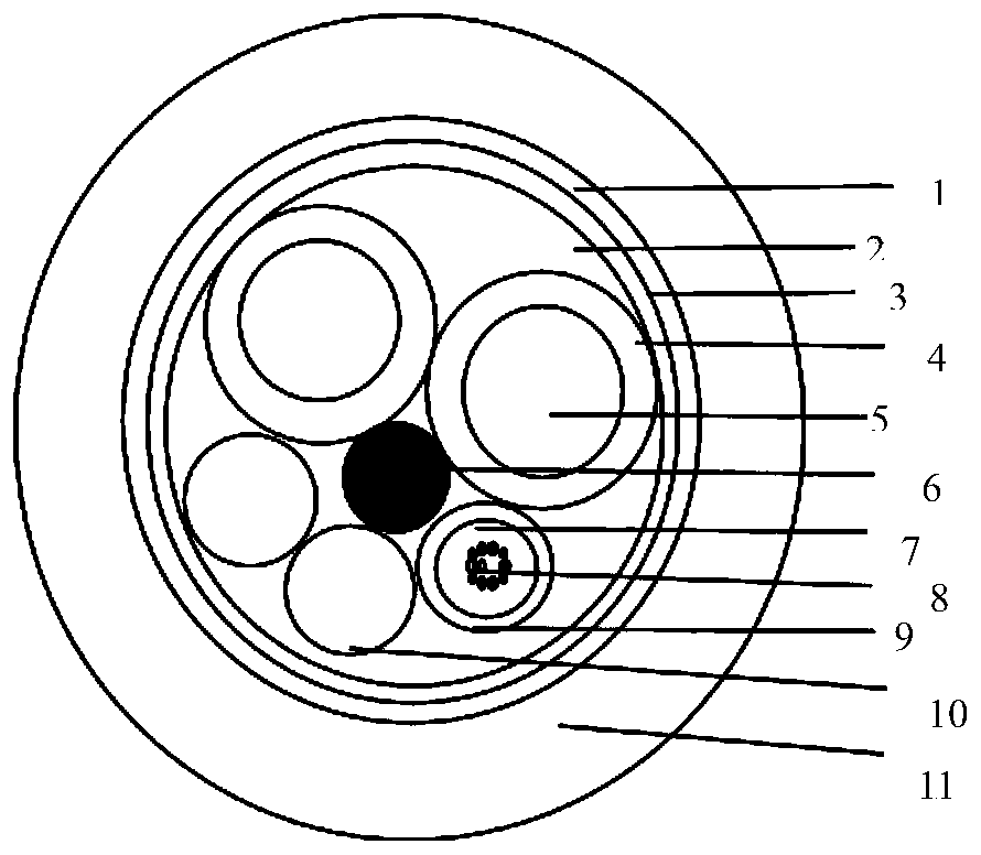
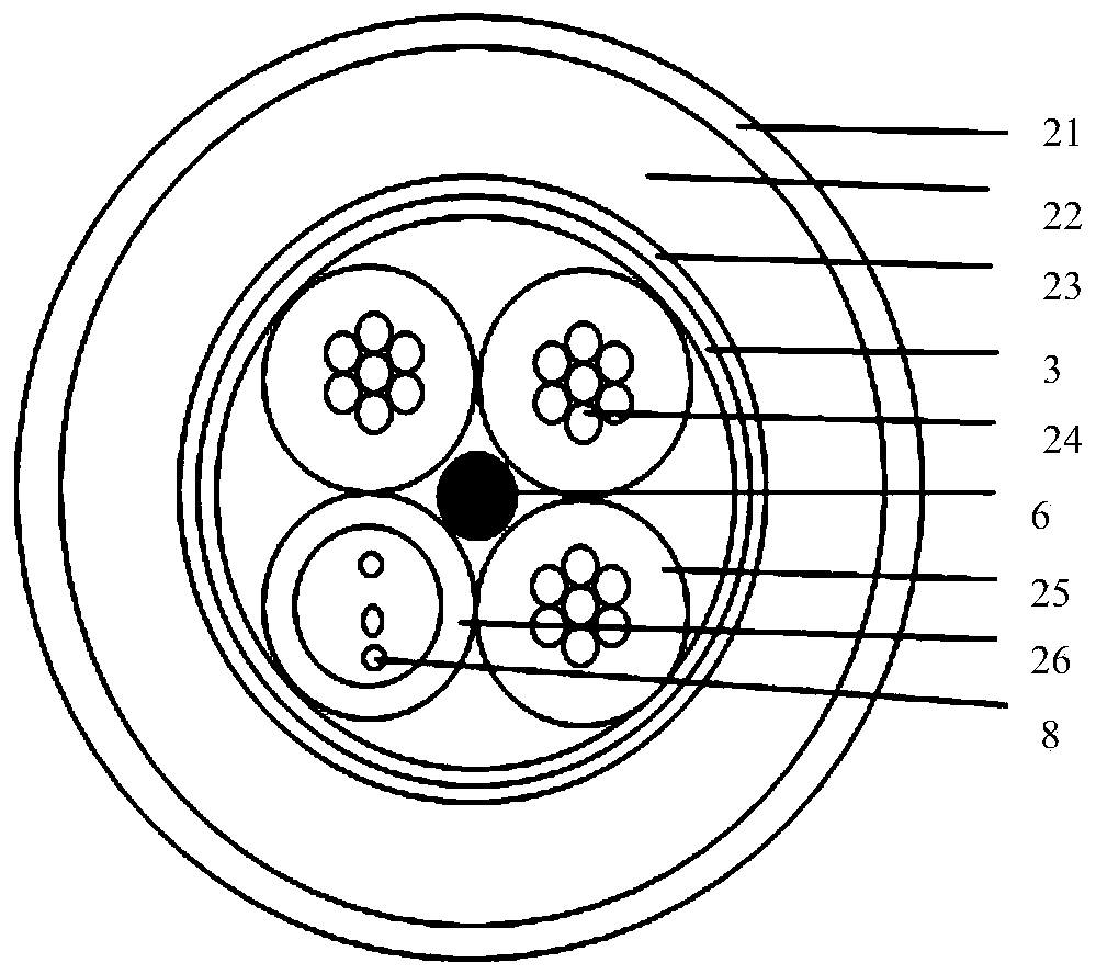
[0035] The structure diagram of optical fiber composite cable is as follows: figure 2 As shown, it includes a cable core and a central reinforcement 6, the cable core includes a plurality of electrical units 24 and an optical unit; each electrical unit 24 is provided with an insulating layer 25, and the optical unit includes a sleeve 26 and is located in the sleeve 26 A number of optical fibers; the cable core is longitudinally wrapped with a water-blocking tape 3;

[0036]The outer diameter of the insulating layer 25 in the photo...


PUM

PropertyMeasurementUnit
thicknessaaaaaaaaaa

Abstract

The invention discloses a photoelectric composite cable, and the cable comprises a cable core and a central reinforcement part (6), and is characterized in that the cable core comprises a plurality ofelectric units (24) and an optical unit; an insulating layer (25) is arranged outside each electric unit (24); the optical unit comprises a sleeve (26) and a plurality of optical fibers positioned inthe sleeve (26); a water-blocking tape (3) is longitudinally wrapped outside the cable core; and a stainless steel band (23), a polyethylene sheath (22) and a nylon sheath (21) are sequentially arranged outside the water-blocking tape (3). The photoelectric composite cable disclosed by the invention has the characteristics that each unit is fixed stably, the mechanical property can be met, the environmental property can be met and the like.

Description

technical field [0001] The invention belongs to the technical field of communication optical cable manufacturing, and relates to a composite cable, in particular to a photoelectric composite cable. Background technique [0002] Conventional photoelectric composite cables generally adopt a 1+4 or 1+5 structure, such as figure 1 As shown, it usually adopts high-strength auxiliary reinforcements, and the electric units are generally two or four symmetrical. The structure is generally not round, and the internal structural units are not easy to produce relative sliding. Layer, the steel strip is pressed into a toothed steel strip with a depth of 0.5-0.6mm through an embossing machine. The steel strip is easy to bend and form, which increases the bending performance of the optical cable. A layer of polyethylene about 1.8mm is extruded outside the steel strip The sheath material forms the first protective wall, which can pass the environmental performance and mechanical performan...

Claims


Application Information

Patent Timeline
Patent Type & Authority Applications(China)
IPC IPC(8): H01B7/22H01B7/282H01B7/285H01B7/18H01B7/02H01B7/17H01B7/28H01B7/29H01B3/44H01B13/02H01B13/24H01B13/26H01B13/32G02B6/44
CPCG02B6/443G02B6/4432H01B3/441H01B7/02H01B7/17H01B7/187H01B7/188H01B7/22H01B7/225H01B7/2806H01B7/2825H01B7/285H01B7/29H01B13/02H01B13/24H01B13/2613H01B13/32
Inventor 王博东林国平张月雷范志香耿军翟徐徐
Owner INST OF HIGH ENERGY PHYSICS CHINESE ACAD OF SCI
Why Eureka
Try Eureka