Cable applied to battery voltage sampling of new energy electric vehicle and production process thereof
A voltage sampling and new energy technology, which is applied in the direction of insulated cables, cable/conductor manufacturing, cables, etc., can solve problems such as intermittent crushing of core wires, difficult cable installation, and irregular core wire structures, and achieve inductance and resistance Stabilize and improve the effect of acquisition accuracy
- Summary
- Abstract
- Description
- Claims
- Application Information
AI Technical Summary
Problems solved by technology
Method used
Image
Examples
Embodiment 1
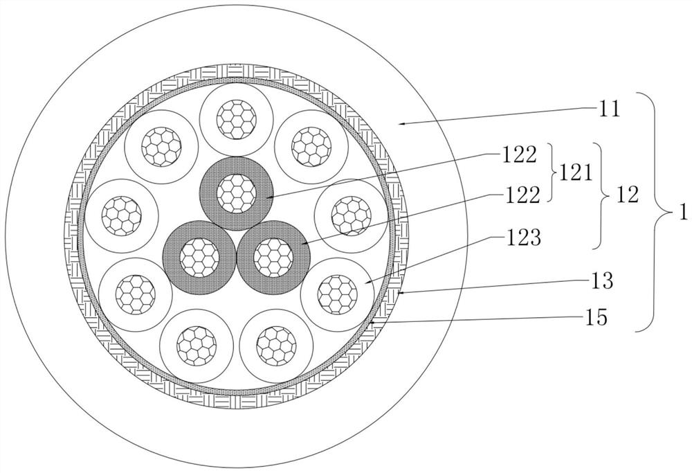
[0034] like figure 1 As shown, the cable of this embodiment includes a cable body 1. The cable body 1 includes a cable outer layer 11 and a core wire cluster 12. The core wire cluster 12 includes an inner layer core wire formed by forward twisting of three inner layer core wires 122. Tufts 121, 9 reversely twisted and wrapped outer core wires 123 of the inner core wire cluster 121, the twist distance of the inner core wire cluster 121 is 65-70mm, the diameter of the inner core wire 122 and the outer core wire 123 They are all the same, the periphery of the core wire cluster 12 is wrapped with a PET polyester tape 15, the periphery of the PET polyester tape 15 is wrapped with a shielding layer 13, the shielding layer 13 is a wire braided mesh, and the outer layer 11 of the cable is wrapped with the shielding layer 13. peripheral.
[0035] Below is the production process of the cable described in this embodiment:
[0036] Step 1: Use 3 inner layer core wires 122 to carry out f...
Embodiment 2
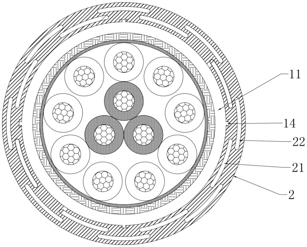
[0047] like figure 2 As shown, the cable in this embodiment includes all the features of the cable described in Embodiment 1; the cable in this embodiment also includes a buffer sleeve 2 wrapped around the outer layer 11 of the cable, and the outer layer 11 of the cable is provided with a second A T-shaped tooth 14, the inner wall of the buffer sleeve 2 is provided with a first T-shaped tooth groove that cooperates with the first T-shaped tooth 14, and the buffer sleeve 2 is provided with several centrally symmetrical first buffer chambers 21, several centrally symmetrical and parallel The second buffer chamber 22 is dislocated from the first buffer chamber 21 .
[0048] The cable production process of the present embodiment comprises all steps of the production process described in embodiment 1, and also includes the following steps:
[0049] Step 6a, the second extrusion die extrudes the buffer sleeve 2, the cable body 1 made in step 5 passes through the buffer sleeve 2, s...
Embodiment 3
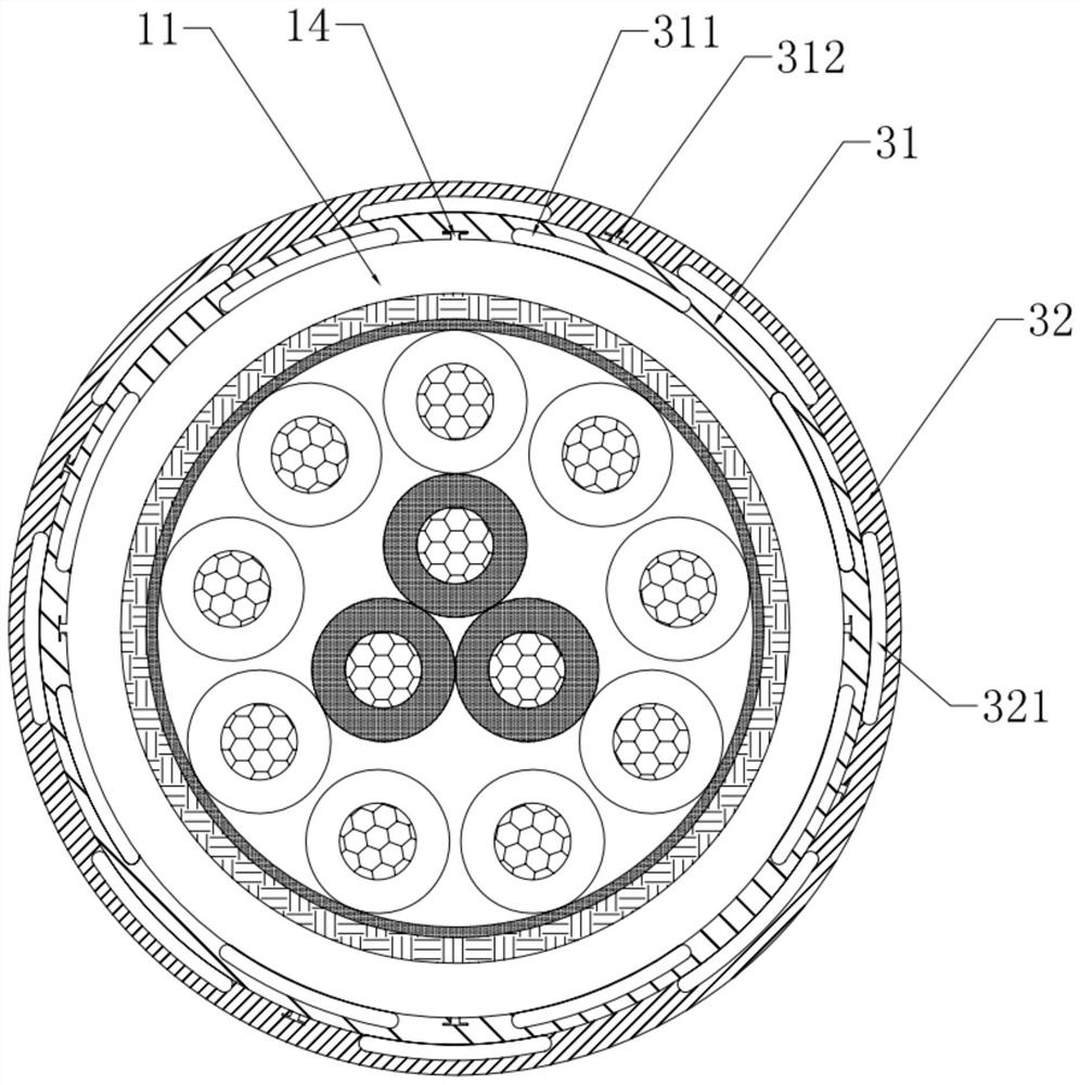
[0051] like image 3 As shown, the cable in this embodiment includes all the features of the cable described in Embodiment 1; the cable in this embodiment also includes a first buffer layer 31 wrapped around the outer layer 11 of the cable, and wrapped around the outer layer of the first buffer layer 31. The second buffer layer 32, the outer periphery of the cable outer layer 11 is provided with a first T-shaped tooth 14, the inner wall of the first buffer layer 31 is provided with a second T-shaped tooth groove that cooperates with the first T-shaped tooth 14, and the cable The outer wall of the outer layer 11 is fitted with the first buffer groove 311 of the parallel cavity, the outer wall of the first buffer layer 31 is provided with a second T-shaped tooth 312, and the inner wall of the second buffer layer 32 is provided with a second T-shaped tooth 312. The third T-shaped tooth groove, the second buffer groove 321 that cooperates with the outer wall of the first buffer la...
PUM
| Property | Measurement | Unit |
|---|---|---|
| tensile strength | aaaaa | aaaaa |
| elongation | aaaaa | aaaaa |
Abstract
Description
Claims
Application Information
 - R&D
- Intellectual Property
- Life Sciences
- Materials
- Tech Scout
- Unparalleled Data Quality
- Higher Quality Content
- 60% Fewer Hallucinations
Browse by: Latest US Patents, China's latest patents, Technical Efficacy Thesaurus, Application Domain, Technology Topic, Popular Technical Reports.
© 2025 PatSnap. All rights reserved.Legal|Privacy policy|Modern Slavery Act Transparency Statement|Sitemap|About US| Contact US: help@patsnap.com


