Optical pulse wave image measuring instrument and pulse type measuring method

A technology of image measurement and pulse wave, applied in the direction of using light for diagnosis, catheterization, etc., can solve the problems affecting the accuracy of pulse diagnosis results and complicated operation methods, achieve objective and accurate pulse condition measurement results, and avoid result errors Effect

Inactive Publication Date: 2020-01-24
LARGAN PRECISION
View PDF13 Cites 2 Cited by
  • Summary
  • Abstract
  • Description
  • Claims
  • Application Information

AI Technical Summary

Problems solved by technology

However, although the above-mentioned pulse diagnosis detector can avoid the result error caused by the palpation habits of different Chinese physicians, it still needs to exert pressure on the patient's wrist with external force and perform contact diagnosis to obtain the relative pulse pressure signal for follow-up. The determination of the pulse diagnosis results is not only complicated in the operation method, but also may affect the accuracy of the pulse diagnosis results due to the contact pulse method

Method used


Image

  • Optical pulse wave image measuring instrument and pulse type measuring method
  • Optical pulse wave image measuring instrument and pulse type measuring method
  • Optical pulse wave image measuring instrument and pulse type measuring method

Examples


Embodiment Construction

[0052] Various embodiments of the present invention will be described below with reference to the accompanying drawings. For the sake of clarity, many practical details are included in the following narrative. It should be understood, however, that these practical details should not be used to limit the invention. That is, in some embodiments of the present invention, these practical details are unnecessary. In addition, for the sake of simplifying the drawings, some known and commonly used structures and elements will be shown in a simple and schematic manner in the drawings; and repeated elements may be denoted by the same numerals.

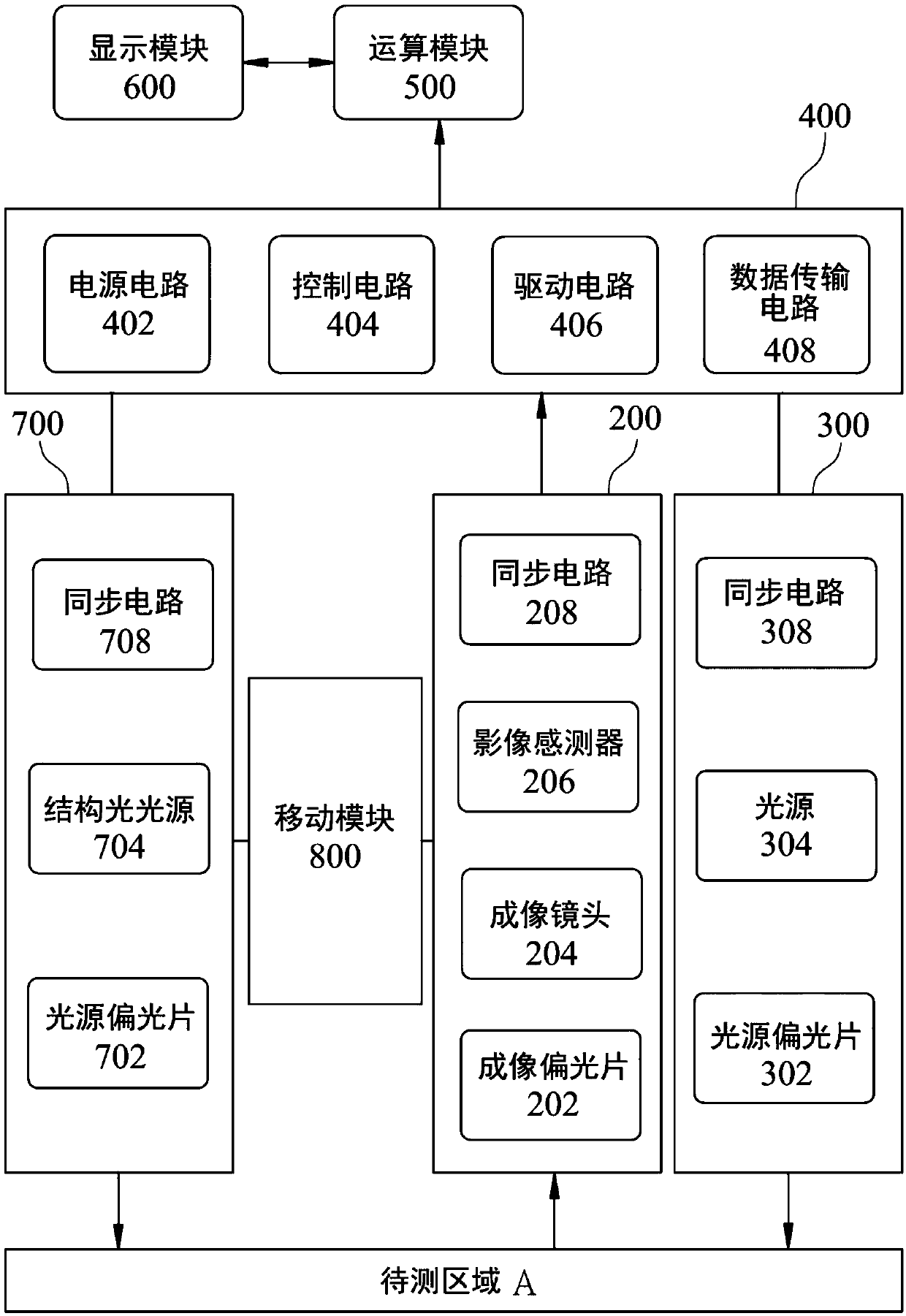
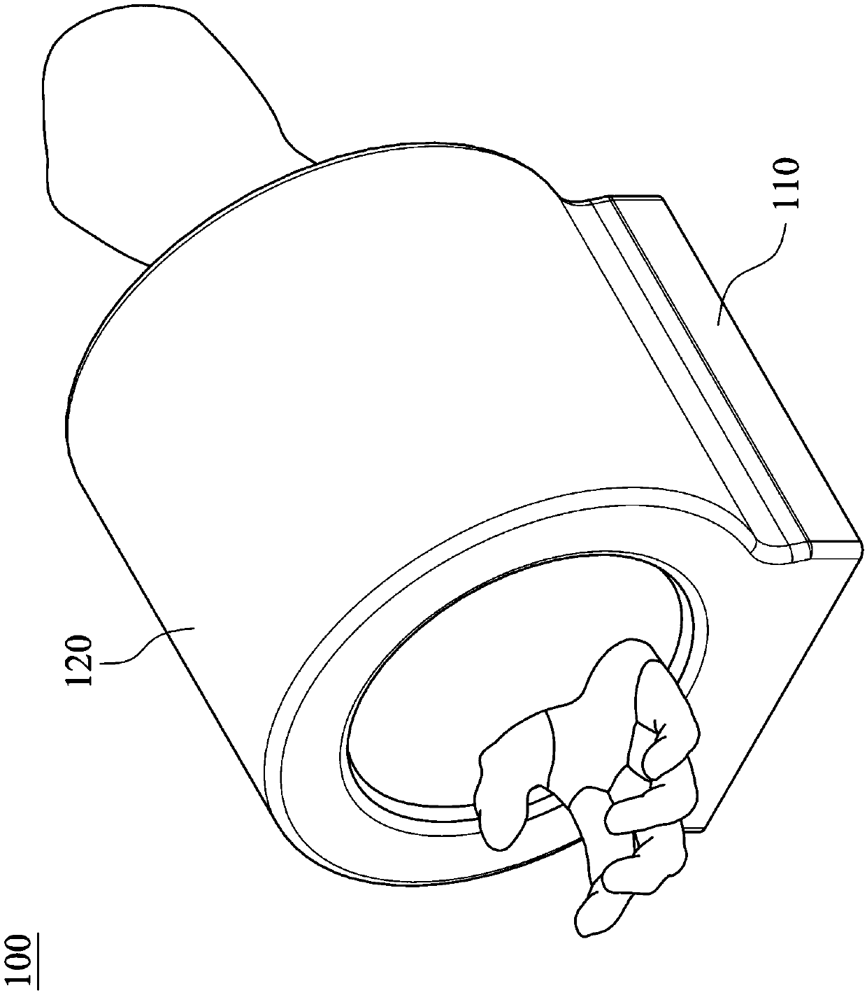
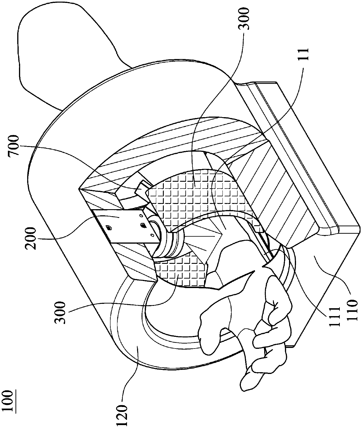
[0053] Please refer to figure 1 , figure 2 and image 3 , figure 1 It is a schematic diagram showing the structure of an optical pulse wave image measuring instrument according to an embodiment of the present invention, figure 2 It is a schematic diagram illustrating an optical pulse wave image measuring instrument 100 of an example of ...


PUM


Abstract

The invention provides an optical pulse wave image measuring instrument and a pulse image measuring method. The optical pulse wave image measuring instrument includes a base, a cover, an imaging module, a light source module, a structured light projection device, a circuit module, a computing module and a display module. The outer cover is disposed on the base. The imaging module is disposed in the outer cover, and is used for capturing an image of an area to be measured. The light source module is disposed on one side of the imaging module. The structured light projection device is disposed inside the cover. The circuit module is electrically connected to the imaging module and the light source module. The operation module signal is connected to the circuit module. The display module signal is connected to the operation module. The optical pulse wave image measuring instrument of the present invention can be used to capture the pulse wave image at the wrist area of the subject and visualize the pulse information to obtain a highly accurate pulse measurement result.

Description

technical field [0001] The invention relates to a pulse condition measuring instrument, in particular to an optical pulse wave image measuring instrument which uses an optical imaging system to measure and analyze the pulse wave image. Background technique [0002] In the traditional pulse-taking process, Chinese physicians press the radial artery of the patient's wrist through actions such as touching, touching, and pressing to feel the pulse conditions of the three pressing depths of the patient's wrists, namely Cun, Guan, and Chi, at three pressing depths: floating, middle, and sinking. Different pressure changes are used to sense different pulse conditions. However, the accuracy of pulse diagnosis will vary due to the different palpation positions, palpation habits and pressing pressure of different Chinese medicine practitioners, and it is impossible to describe the pulse condition objectively. Variability, making it easier to issue false diagnoses to patients. [000...

Claims


Application Information

Patent Timeline
Patent Type & Authority Applications(China)
IPC IPC(8): A61B5/02
CPCA61B5/02A61B5/0059
Inventor 黄澄儀谢易振柯昱成蔡钧涵许庭铨
Owner LARGAN PRECISION
Why Eureka
Try Eureka