Locking control method and device of steelmaking desulphurization molten iron tipping vehicle

A locking device, a technology for desulfurized molten iron, which is applied in the direction of manufacturing tools, casting melt containers, metal processing equipment, etc., and can solve problems such as easily damaged locking equipment.

Active Publication Date: 2020-01-24
SHOUGANG JINGTANG IRON & STEEL CO LTD
View PDF6 Cites 0 Cited by
  • Summary
  • Abstract
  • Description
  • Claims
  • Application Information

AI Technical Summary

Problems solved by technology

[0004] After the existing locking mechanism is locked, there is no shaking space between the tilting device and the locking device. In this way, w

Method used


Image

  • Locking control method and device of steelmaking desulphurization molten iron tipping vehicle
  • Locking control method and device of steelmaking desulphurization molten iron tipping vehicle
  • Locking control method and device of steelmaking desulphurization molten iron tipping vehicle

Examples


Embodiment 1

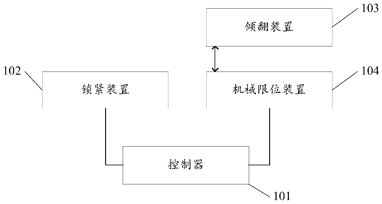
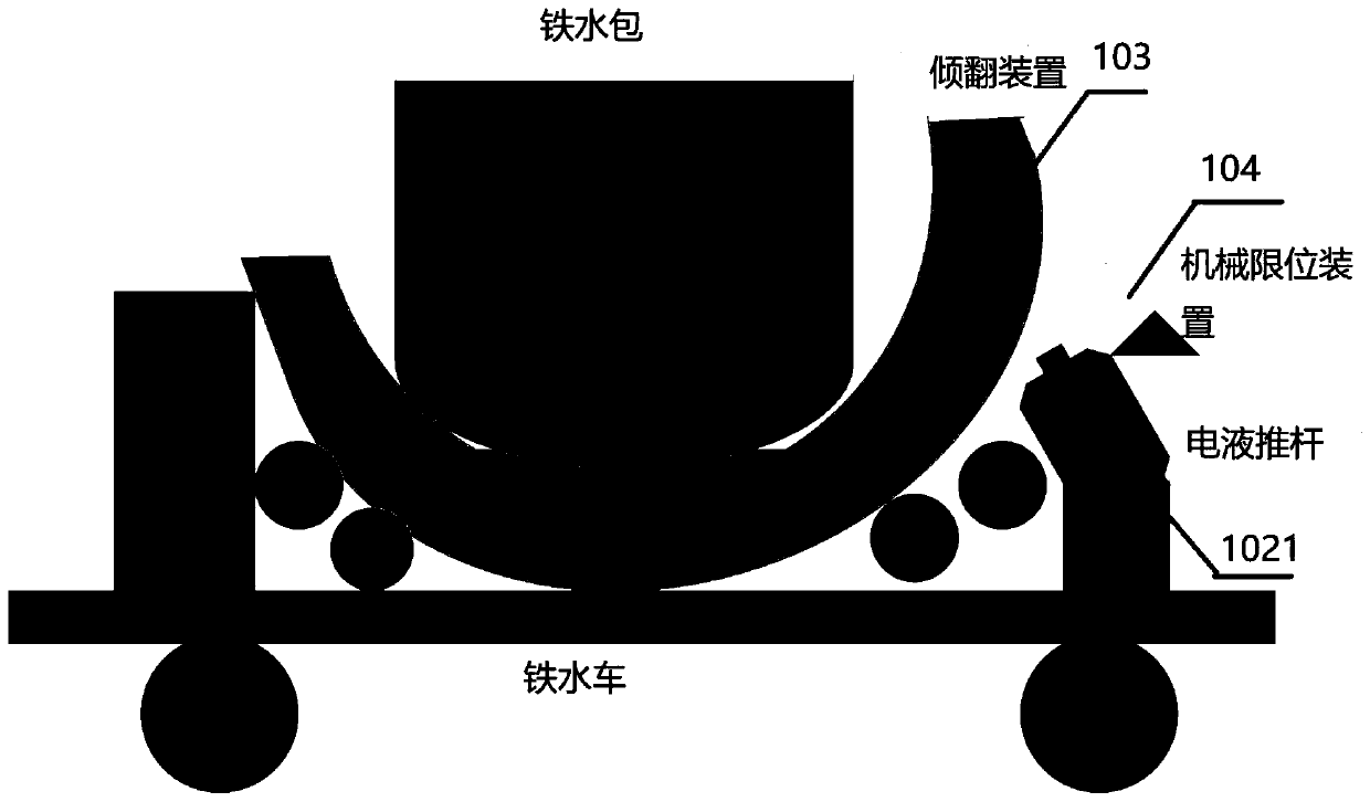
[0045] An embodiment of the present invention provides a locking control device for a steelmaking desulfurization molten iron tipping car, such as figure 1 As shown, it includes: a controller 101 , a locking device 102 , a tipping device 103 , and a mechanical limit device 104 , wherein the controller 101 is connected to the locking device 102 and the mechanical limit device 103 .

[0046] Wherein, the tilting device 103 is used to carry the ladle. When the tilting device is vertically placed, the molten iron can be placed horizontally, and when the tilting device is rotated, the molten iron can be tilted.

[0047] The locking device 102 is used to start operation and point to the tipping device 103 based on the locking command;

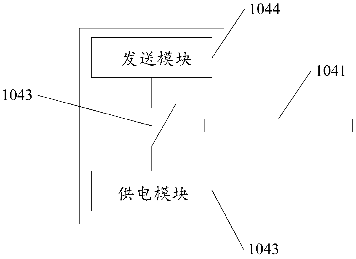
[0048] The mechanical limit device 104 is used to generate a limit pulse signal and feed it back to the controller 101 when it is detected that the locking device 102 has moved to a preset limit;

[0049] The controller 101 is used to control the lo...

Embodiment 2

[0066] Based on the same inventive concept, an embodiment of the present invention also provides a locking control method for a steelmaking desulfurization molten iron tipping car, which is applied to a locking control device for a steelmaking desulfurization tipping car. The device includes: a controller, a locking device, tipping device, mechanical limit device, such as Figure 4 Shown: includes:

[0067] S401, generating a locking instruction;

[0068] S402. Based on the locking instruction, control the locking device to operate and point to the tilting device;

[0069] S403. Receive a limit pulse signal, where the limit pulse signal is specifically a limit pulse signal generated when the mechanical limit device detects that the locking device has moved to a preset limit;

[0070] S404. Based on the actual effective duration of the limit pulse signal, control the locking device to run in reverse for a preset duration on the falling edge of the limit pulse signal and then ...


PUM


Abstract

The invention relates to the technical field of iron and steel smelting, in particular to a locking control method and device of a steelmaking desulphurization molten iron tipping vehicle. The lockingcontrol method is applied to a steelmaking desulphurization tipping vehicle locking control device. The locking control device comprises a controller, a locking device, a tipping device and a mechanical limiting device. The locking control method comprises the steps of controlling the locking device to operate and point to the tipping device based on a locking instruction; receiving a limiting pulse signal which is generated when the mechanical limiting device detects the locking device to operate to the preset limiting position; and controlling the locking device to reversely operate for thepreset time duration and then stop operating at the falling edge of the limiting pulse signal on the basis of the actual effective time duration of the limiting pulse signal, wherein the preset timeduration specifically accounts for one-third of the actual effective time duration. Through the locking control method and device, it is ensured that the tipping device has a shaking space after a ladle is placed on the tipping device, so that molten iron in the ladle is not likely to be splashed out during running of the steelmaking desulphurization molten iron tipping vehicle. Thus, contact damage cannot occur to the locking device and the tipping device.

Description

technical field [0001] The invention relates to the technical field of iron and steel smelting, in particular to a locking control method and device for a steelmaking desulfurization molten iron tipping car. Background technique [0002] When the tipping vehicle for steel-making desulfurization molten iron is vertical, use the crane to lift the molten iron ladle and place it on the tipping equipment, and lock the tipping equipment to prevent the ladle from being The molten iron in the ladle is splashed out; the tilting device is unlocked so that the tilting device is in a tilted state, and the slag removal operation is performed on the ladle. [0003] Wherein, before the molten iron ladle is hoisted by the crane and placed on the tipping device, the tipping device needs to be locked. [0004] After the existing locking mechanism is locked, there is no shaking space between the tilting device and the locking device. In this way, when the ladle is placed on the tilting device...

Claims


Application Information

Patent Timeline
IPC IPC(8): B22D41/12B22D41/06C21C7/064
CPCB22D41/06B22D41/12C21C7/0075C21C7/064
Inventor 王景娟吕永学张丙龙曾卫民王和兵吴耀春王胜秦登平赵长亮孟志铎张坤
Owner SHOUGANG JINGTANG IRON & STEEL CO LTD
Why Eureka
Try Eureka