Flow valve used for hydraulic oil cylinder and facilitating hydraulic control proportion

A hydraulic cylinder and flow valve technology, applied in the field of hydraulic cylinders, can solve the problems of affecting the interception effect, affecting the quality of materials, poor sealing, etc., achieving the effect of convenient installation and use, and improving transmission quality

Active Publication Date: 2020-01-24
JIANHU BADA HYDRAULIC MACHINERY CO LTD
View PDF5 Cites 0 Cited by
  • Summary
  • Abstract
  • Description
  • Claims
  • Application Information

AI Technical Summary

Problems solved by technology

[0004] The purpose of the present invention is to provide a flow valve for a hydraulic cylinder with a convenient hydraulic control ratio, so as to solve the problem that in the flow process of the material in the existing flow valve proposed in the above-mentioned background technology, the impurity doped in the material will affect the flow rate of the material. The quality of the material, and the material can only flow in one ratio, and the poor sealing performance of the interception will affect the interception effect

Method used


Image

  • Flow valve used for hydraulic oil cylinder and facilitating hydraulic control proportion
  • Flow valve used for hydraulic oil cylinder and facilitating hydraulic control proportion
  • Flow valve used for hydraulic oil cylinder and facilitating hydraulic control proportion

Examples


Embodiment Construction

[0028] The following will clearly and completely describe the technical solutions in the embodiments of the present invention with reference to the accompanying drawings in the embodiments of the present invention. Obviously, the described embodiments are only some, not all, embodiments of the present invention. Based on the embodiments of the present invention, all other embodiments obtained by persons of ordinary skill in the art without making creative efforts belong to the protection scope of the present invention.

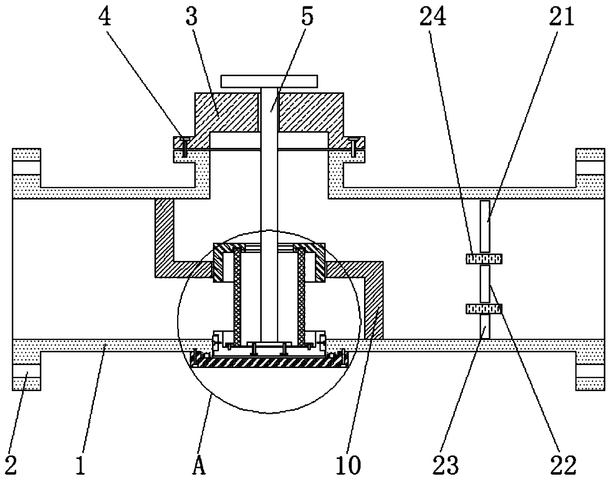
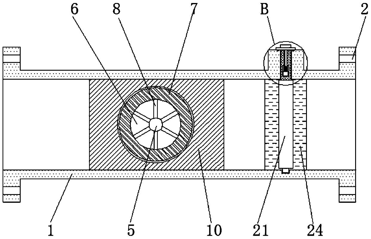
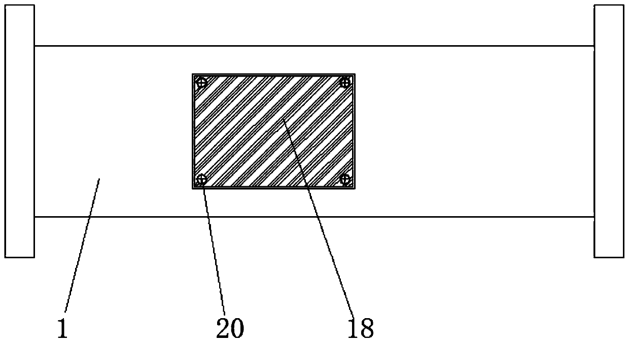
[0029] see Figure 1-7 , the present invention provides a technical solution: a flow valve for a hydraulic cylinder with a convenient hydraulic control ratio, according to figure 1 with figure 2 As shown, including valve body 1, threaded rod 5, fixed frame 10 and second bottom plate 18, the left and right sides of valve body 1 are provided with mounting holes 2, and the mounting holes 2 are evenly distributed on the left and right sides of valve body 1, the ...


PUM


Abstract

The invention discloses a flow valve used for a hydraulic coil cylinder and facilitating a hydraulic control proportion. The flow valve comprises a valve body, a thread rod, a fixed frame and a secondbottom plate. The thread rod penetrates through a sleeve and a first through hole, second through holes are formed in the bottom of the valve body and the fixed frame, the upper side of a first bottom plate is fixedly provided with a filter frame through a third bolt, a first rotating plate, a second rotating plate and a third rotating plate are arranged on the right side of the fixed frame, fixed plates are arranged on the upper side and the lower side of the second rotating plate, rotating rods are fixed to the rear side of the first rotating plate, the rear side of the second rotating plate and the rear side of the third rotating plate, a sliding block is arranged on the front side of a compression spring, and a safe rotating frame is fixed to the rear side of the sliding block. According to the flow valve used for the hydraulic coil cylinder and facilitating the hydraulic control proportion, the safe rotating frame is backwards pulled and then rotated until the first rotating plate or the second rotating plate or the third rotating plate is rotated to the horizontal state from the vertical state, at the moment, the material flows through the first rotating plate or the secondrotating plate or the third rotating plate, and the hydraulic control proportion is finished.

Description

technical field [0001] The invention relates to the technical field of hydraulic cylinders, in particular to a flow valve for hydraulic cylinders with convenient hydraulic control ratio. Background technique [0002] The hydraulic cylinder is a hydraulic actuator that converts hydraulic energy into mechanical energy and performs linear reciprocating motion. It has a simple structure and reliable operation. When it is used to realize reciprocating motion, the deceleration device can be eliminated, and there is no transmission gap, and the motion is stable. Therefore It is widely used in various mechanical hydraulic systems, and the hydraulic cylinder needs to use a flow valve to control the oil volume when the oil is discharged. [0003] During the flow of the material in the existing flow valve, impurities doped in the material will affect the quality of the material, and the material can only flow in one proportion, and the poor sealing performance will affect the blocking ...

Claims


Application Information

Patent Timeline
Patent Type & Authority Applications(China)
IPC IPC(8): F15B13/02F15B21/041
CPCF15B13/021F15B21/041
Inventor 严恺商雨楼
Owner JIANHU BADA HYDRAULIC MACHINERY CO LTD
Why Eureka
Try Eureka