
Metal sealing valve seat and wear-resisting ball valve

A metal seal, wear-resistant ball technology, applied in shaft seals, valve details, valve devices, etc., can solve the problems of long service life, operation force consumption, poor effect, etc., and achieve the effect of improving service life

Pending Publication Date: 2020-01-24
SANBORA VALVE
View PDF5 Cites 0 Cited by
  • Summary
  • Abstract
  • Description
  • Claims
  • Application Information

AI Technical Summary

Problems solved by technology

[0005] The sealing effect of the valve seat and wear-resistant ball valve in the prior art is poor, and the service life needs to be improved. At the same time, it is inconvenient to operate and relatively labor-intensive. Therefore, it is urgent to develop a metal-sealed valve seat and wear-resistant ball valve.

Method used


Image

  • Metal sealing valve seat and wear-resisting ball valve
  • Metal sealing valve seat and wear-resisting ball valve
  • Metal sealing valve seat and wear-resisting ball valve

Examples


Embodiment Construction

[0025] In order to make the above objects, features and advantages of the present invention more comprehensible, specific implementations of the present invention will be described in detail below in conjunction with the accompanying drawings.

[0026] In the following description, a lot of specific details are set forth in order to fully understand the present invention, but the present invention can also be implemented in other ways different from those described here, and those skilled in the art can do it without departing from the meaning of the present invention. Similarly generalized, the present invention is therefore not limited by the specific embodiments disclosed below.

[0027] Secondly, the present invention is described in detail in conjunction with schematic diagrams. When describing the implementation of the present invention in detail, for the convenience of explanation, the cross-sectional view showing the device structure will not be partially enlarged accor...


PUM


Abstract

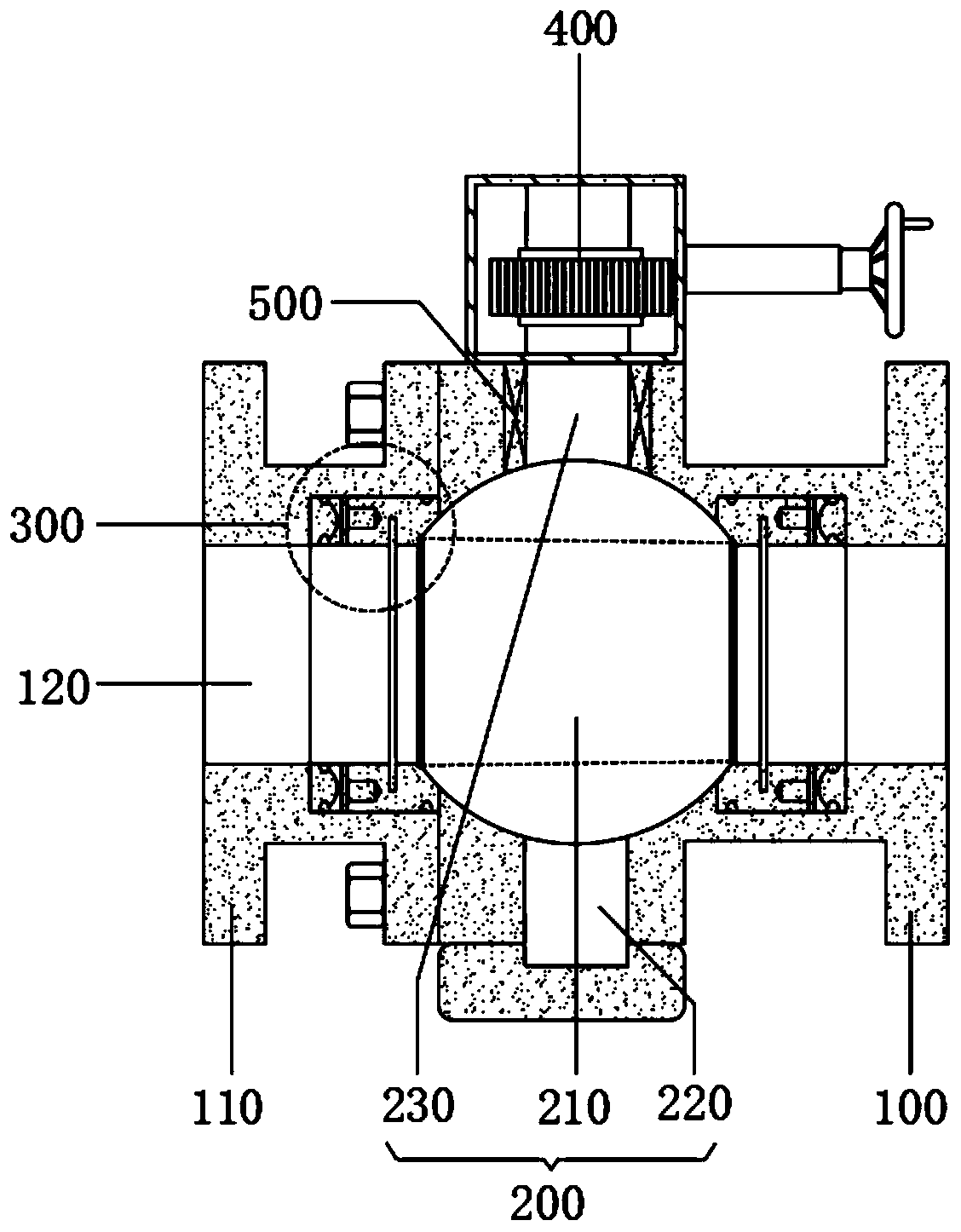
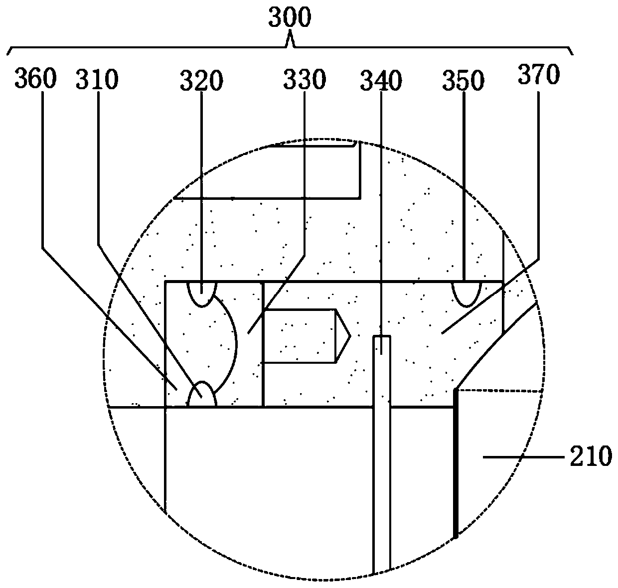
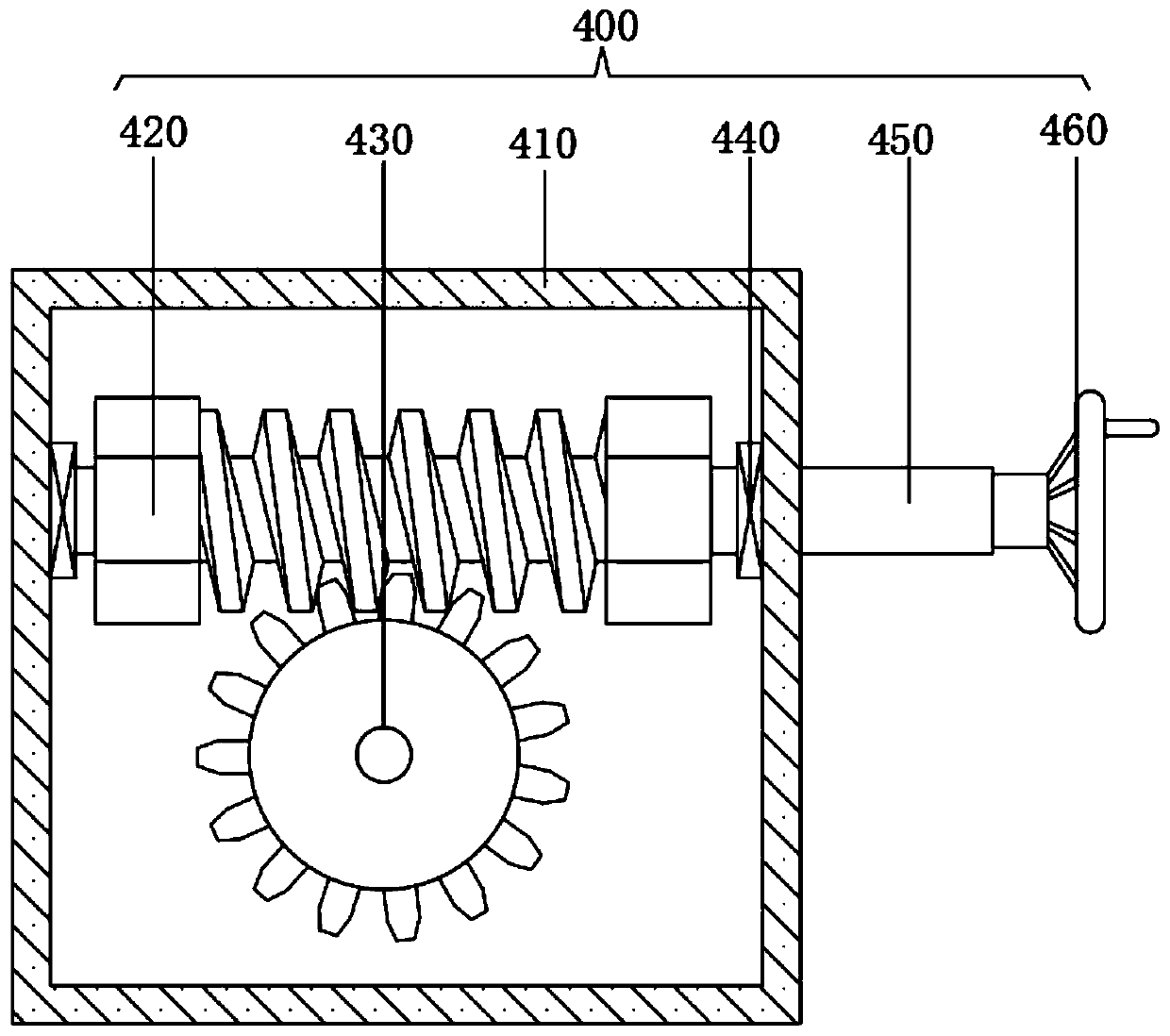
The invention belongs to the technical field of ball valves, and specifically relates to a metal sealing valve seat and a wear-resisting ball valve. The metal sealing valve seat and the wear-resistantball valve comprise a valve body I, a ball body assembly, valve seat assemblies and a manual operation assembly, wherein a valve body II is fixedly arranged on the left side wall of the valve body I,through holes are formed in the valve body II and the left and right directions of the middle part of the valve body II correspondingly, the ball body assembly is arranged at the inner wall of the valve body I, the valve seat assemblies are fixedly arranged in the left and right directions of the inner walls of the through holes, the valve seat assemblies are located on the left side and the right side of the ball body assembly correspondingly, and the manual operation assembly is fixedly arranged on the top of the valve body I. According to the metal sealing valve seat and a wear-resisting ball valve, the sealing effect is improved, the service life is prolonged, and meanwhile, the comprehensive effect of the labor-saving function is achieved.

Description

technical field [0001] The invention relates to the technical field of ball valves, in particular to metal sealing valve seats and wear-resistant ball valves. Background technique [0002] Ball valve, the opening and closing part (ball) is driven by the valve stem and rotates around the axis of the ball valve. It can also be used for the regulation and control of fluids, among which the hard-sealed V-shaped ball valve has a strong shear force between its V-shaped ball core and the metal valve seat of surfacing welding carbide, and is especially suitable for fibers and tiny solid particles. etc. medium. The multi-way ball valve can not only flexibly control the confluence, diversion, and flow direction switching of the medium on the pipeline, but also close any channel and connect the other two channels. This type of valve should generally be installed horizontally in the pipeline. According to the driving mode, the ball valve is divided into: pneumatic ball valve, electri...

Claims


Application Information

Patent Timeline
Patent Type & Authority Applications(China)
IPC IPC(8): F16K5/06F16K5/08F16K5/20F16K27/06F16K31/53F16K31/60F16K41/02
CPCF16K5/0605F16K5/08F16K5/201F16K27/067F16K31/60F16K31/53F16K5/0694
Inventor 王邦捷
Owner SANBORA VALVE
Learn More