Driving type expansion joint and application thereof

A telescopic joint and drive-type technology, applied in the direction of adjustable connections, pipes/pipe joints/fittings, passing components, etc., can solve problems such as labor-intensive, large air leakage rate, inconvenient operation, etc., to prevent collision accidents and equipment damage, Improve duct ventilation and reduce air leakage rate

Inactive Publication Date: 2020-01-24
NINGXIA SEN SOURCE HEAVY EQUIP
View PDF6 Cites 1 Cited by
  • Summary
  • Abstract
  • Description
  • Claims
  • Application Information

AI Technical Summary

Problems solved by technology

In the process of ventilation or dust collection, there are no reliable sealing or compensation measures for the gaps, and the air leakage rate is large, which affects the ventilation or dust collection effect
In the actual application of the vacuum cover, measures such as manual winding of flexible materials are also taken to reserve gaps to avoid collisions. However, due to the limited installation height and space when implementing measures such as winding flexible materials, it results in labor-intensive, time-consuming, and Inconvenient to operate
Until now, there is no convenient and reliable device or measure to solve the air leakage in the gap between the fixed pipe and the switch joint of the vacuum hood

Method used


Image

  • Driving type expansion joint and application thereof
  • Driving type expansion joint and application thereof
  • Driving type expansion joint and application thereof

Examples


Embodiment 1

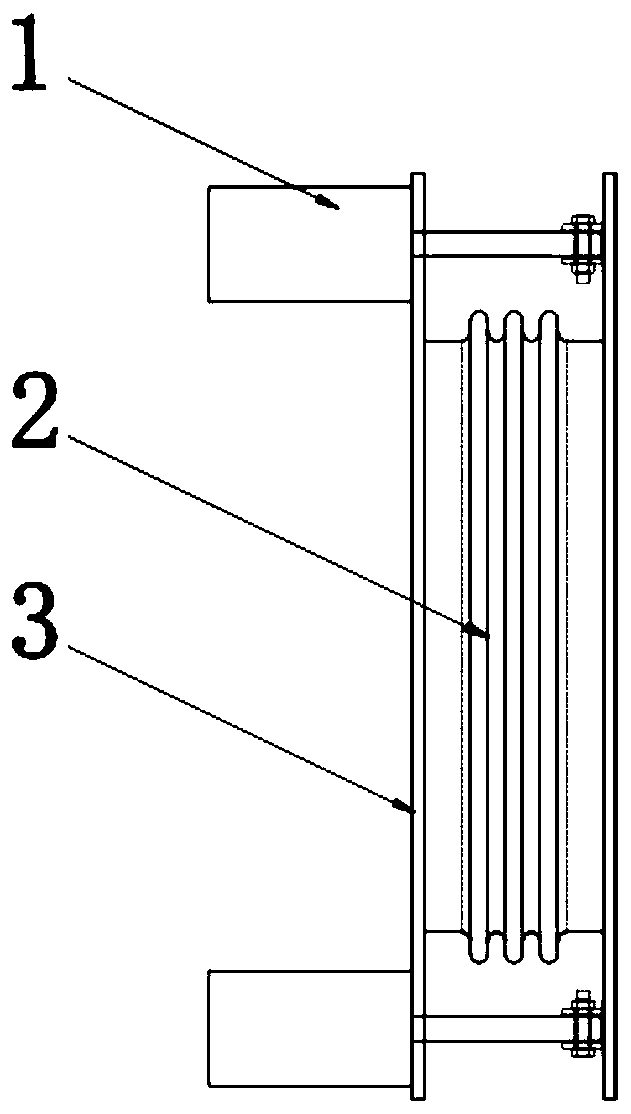
[0022] Such as figure 1 , 2 , 3, 5, and 6, a drive-type telescopic joint, including a telescopic joint main body 2, the two ends of the telescopic joint main body 2 are respectively fixed with end flanges 3, and the end flange 3 at one end A drive mechanism 1 is fixed on it, and the telescopic end of the drive mechanism 1 is connected to the end flange 3 at the other end.

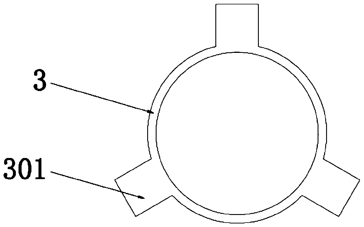
[0023] Connecting ears 301 are arranged at equal intervals on the end flange 3 , and the driving mechanism 1 is mounted on the connecting ears 301 .

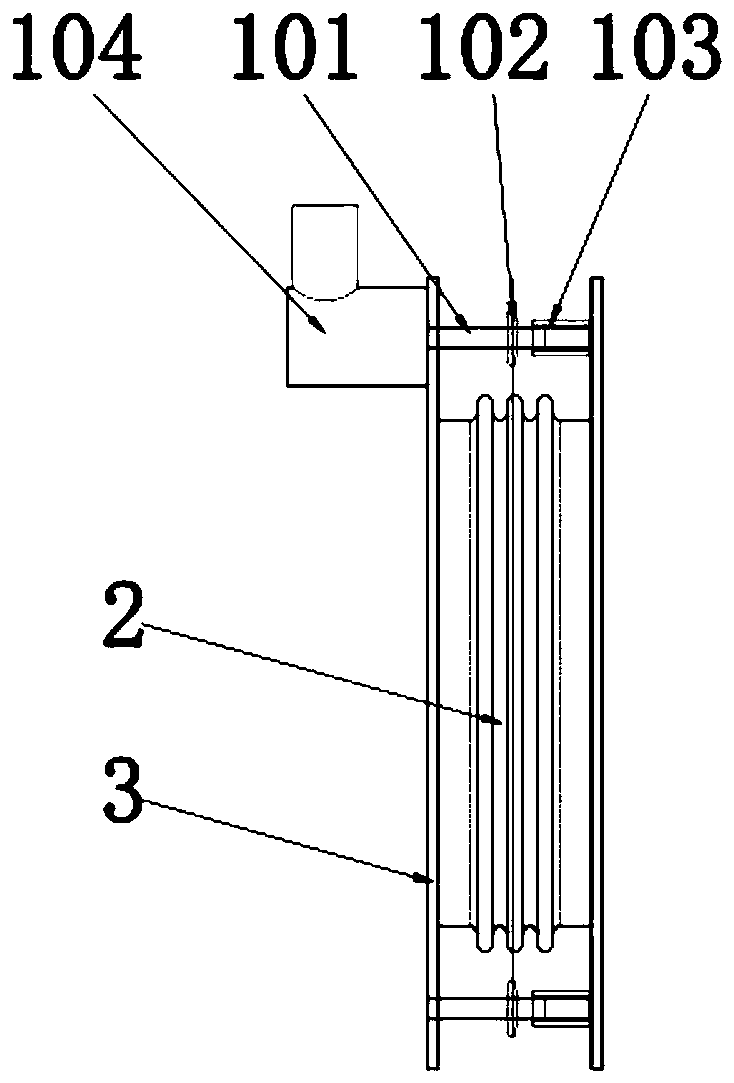
[0024] The driving mechanism 1 is a worm gear reducer 104 . Can be driven manually or electrically.

[0025] The output end of the worm gear reducer 104 is a rotating screw 101, on which a nut sleeve 103 is installed, and the nut sleeve 103 is fixedly connected with the other end flange 3, and the rotating screw 101 A sprocket 102 is also installed on the 101, and the rotating screw mandrels 101 are connected by a chain.

[0026] An application of a driv...

Embodiment 2

[0029] Such as figure 1 , 2 , 4, 5, and 6, a drive-type telescopic joint, including a telescopic joint main body 2, the two ends of the telescopic joint main body 2 are respectively fixed with end flanges 3, and the end flange 3 at one end A drive mechanism 1 is fixed on it, and the telescopic end of the drive mechanism 1 is connected to the end flange 3 at the other end.

[0030] Connecting ears 301 are arranged at equal intervals on the end flange 3 , and the driving mechanism 1 is mounted on the connecting ears 301 .

[0031] The driving mechanism 1 is any one of a cylinder and a hydraulic push rod.

[0032] One end of the air cylinder or hydraulic push rod is fixed on one end flange 3 , and the output end of the air cylinder or hydraulic push rod is fixed on the other end flange 3 .

[0033] An application of a drive type expansion joint, the drive type expansion joint is installed on the guide rail 6, the extended end of the drive type expansion joint is docked with th...


PUM


Abstract

The invention discloses a driving type expansion joint and application thereof. The driving type expansion joint includes an expansion joint main body, the two ends of the expansion joint main body are fixedly provided with end flanges, the end flange at one end is fixedly provided with a driving mechanism, and the telescopic end of the driving mechanism is connected to the end flange at the otherend. The driving type expansion joint can achieve active extension and compression, collision between a dust suction hood and a fixed pipe during movement of the dust suction hood can be avoided, andcollision accidents and equipment damage are avoided; and a gap generated after positioning and docking of the dust suction hood and the fixed pipe can be made up, the air leakage rate is reduced, the pipe ventilation and dust collection efficiency is improved, manual sealing is saved, time and labor are saved, and operation is facilitated.

Description

technical field [0001] The invention belongs to the technical field of pipeline ventilation, and in particular relates to a driving expansion joint and its application. Background technique [0002] In the ventilation or environmental protection dust removal pipeline system, some pipelines or dust collection hood facilities need to frequently move through the track and switch to one or more other fixed pipelines. Sufficient clearance must be left between the pipe axes to avoid collisions. In the process of ventilation or dust collection, there are no reliable sealing or compensation measures for the gaps, and the air leakage rate is large, which affects the ventilation or dust collection effect. In the actual application of the vacuum cover, measures such as manual winding of flexible materials are also taken to reserve gaps to avoid collisions. However, due to the limited installation height and space when implementing measures such as winding flexible materials, it result...

Claims


Application Information

Patent Timeline
Patent Type & Authority Applications(China)
IPC IPC(8): F16L27/12
CPCF16L27/12
Inventor 程树斌李宁
Owner NINGXIA SEN SOURCE HEAVY EQUIP
Why Eureka
Try Eureka