
Bearing housing for turbomachine, and turbomachine having bearing housing

A bearing housing, bearing axis technology, applied to components of pumping devices for elastic fluids, bearing cooling, bearing components, etc., can solve the problem of increased wear, high bearing housing cost, insufficient and expensive cooling technology, etc. problem to achieve the effect of increasing the total surface area

Inactive Publication Date: 2020-01-24
SULZER MANAGEMENT AG
View PDF0 Cites 0 Cited by
  • Summary
  • Abstract
  • Description
  • Claims
  • Application Information

AI Technical Summary

Problems solved by technology

[0004] However, it has been proven in practice that under certain operating conditions (e.g. high outside air temperatures above 50°C), the mentioned cooling techniques are insufficient and expensive, leading to increased wear or even bearing failure or high bearing housing costs

Method used


Image

  • Bearing housing for turbomachine, and turbomachine having bearing housing
  • Bearing housing for turbomachine, and turbomachine having bearing housing
  • Bearing housing for turbomachine, and turbomachine having bearing housing

Examples


Embodiment Construction

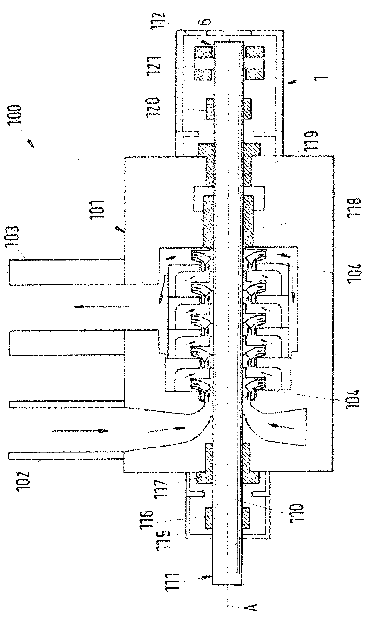
[0030] figure 1 A cross-sectional view of an embodiment of a flow machine according to the invention is shown, the flow machine being denoted with the reference numeral 100 in its units. An example of a flow machine 100 is a centrifugal pump 100 for conveying fluids such as water or crude oil or multiphase liquids. Obviously, the present invention is neither limited to figure 1 The centrifugal pump 100 shown in , is also not limited to the centrifugal pump itself, but generally refers to the flow machine 100 . For example, flow machine 100 may also be another type of pump, compressor, fan, expander, or turbine.

[0031] The centrifugal pump 100 comprises a housing 101 which may consist of a plurality of housing parts connected to each other to form the housing 101 . The housing 101 of the centrifugal pump 100 includes an inlet 102 through which the fluid to be delivered enters the pump 100 , and an outlet 103 for discharging the fluid. At least one impeller 104 is disposed...


PUM


Abstract

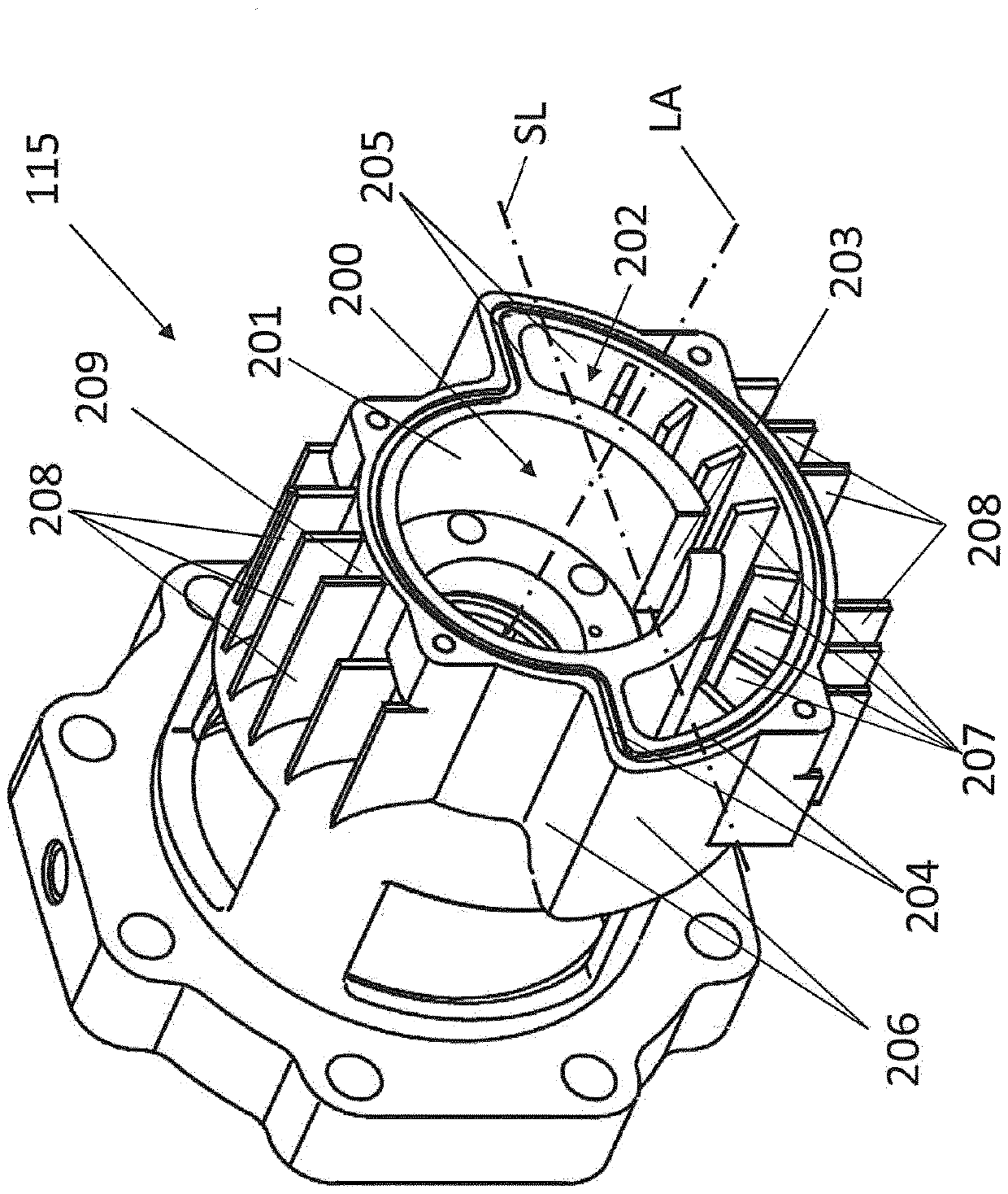
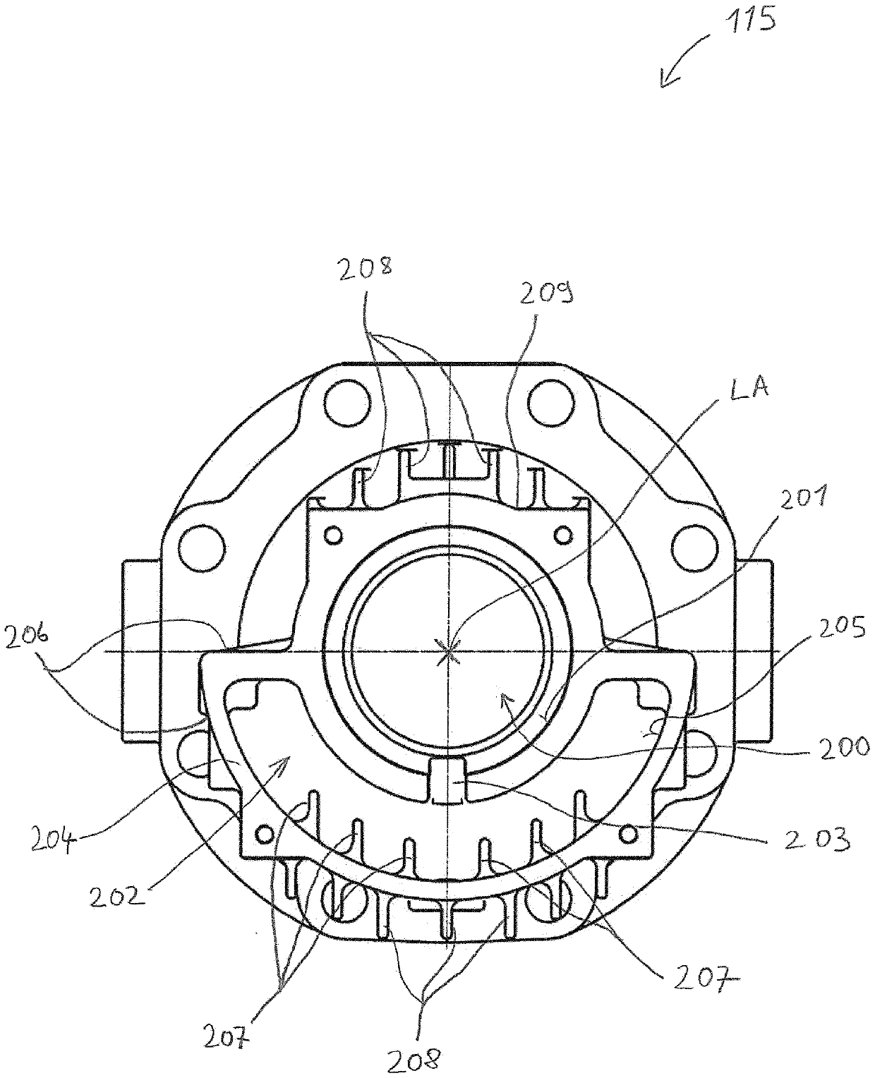
The invention relates to a bearing housing (115) for a turbomachine (100), wherein the bearing housing (115) comprises a bearing axis (LA), a bearing chamber (200) for accommodating a bearing (116, 120, 121), and a lubricant chamber (202) for accommodating a lubricant, and the lubricant chamber (202) and the bearing chamber (200) are fluidically connected via an opening (203), wherein the lubricant chamber (202) comprises a wall portion (204) for releasing heat to the surroundings, which wall portion (204) has an inner surface (205) facing the lubricant chamber (202) and an outer surface (206)facing the surroundings. In order that adequate cooling of the bearing (116, 120, 121) and of the lubricant can be achieved even at high ambient temperatures, internal cooling fins (207) are arrangedon a part of the inner surface (205).

Description

technical field [0001] The invention relates to a bearing housing for a flow machine according to the preamble of independent claim 1 . The invention also relates to a flow machine with a bearing housing according to independent claim 9 . Background technique [0002] Flow machines for conveying fluids (eg, centrifugal pumps, compressors, fans, expanders, or turbines) typically include a stationary machine housing enclosing a rotor (eg, impeller) arranged on a shaft that rotates about the axis of the flow machine superior. The flow machine also has at least one bearing unit with radial and / or axial (thrust) bearings to support the shaft and rotor. Typically, the bearing unit has a separate bearing housing that is firmly connected to the housing of the flow machine. In this case, the bearing housing comprises a bearing axis, a bearing chamber for receiving the bearing and a lubricant chamber for receiving lubricant. The lubricant chamber and the bearing chamber are in flo...

Claims


Application Information

Patent Timeline
Patent Type & Authority Applications(China)
IPC IPC(8): F04D1/06F04D29/047F04D29/58F04D29/06
CPCF04D1/06F04D29/0473F04D29/061F04D29/5893F05D2260/22141F05D2240/53F05D2260/98F16C33/6666F16C37/007F16C2360/44
Inventor A.维尔德
Owner SULZER MANAGEMENT AG
Learn More