
Automatic cooker

A cooking machine and automatic technology, which is applied in the directions of plug-ins, cooker brackets, cooking utensils, etc., can solve problems such as complex structure, and achieve the effect of compact structure optimization and three-dimensional uniform stir-frying function.

Pending Publication Date: 2020-01-31
王学勤
View PDF0 Cites 5 Cited by
  • Summary
  • Abstract
  • Description
  • Claims
  • Application Information

AI Technical Summary

Problems solved by technology

Among them, one is to rely on the rotation of the pot body, which is characterized by a relatively simple structure, and the other is to rely on the swing of the pot body, which is characterized by uniform heating of materials, but the structure is relatively complicated, and the other is to use a stirring shovel in the pot Stirring the materials in the pot belongs to the current common way of stir frying
In addition, in order to further enhance the stir-frying effect, some stir-frying machines will combine the above-mentioned stir-frying techniques in pairs to form a stir-frying machine with two-axis input function, but there is no stir-frying machine that combines the above three stir-frying techniques. Together, so providing a kind of automatic cooking machine with three-axis input function and compact structure has become an urgent problem to be solved in the current industry

Method used


Image

  • Automatic cooker
  • Automatic cooker
  • Automatic cooker

Examples


Embodiment Construction

[0023] In order to describe the technical content and structural features of the present invention in detail, further description will be given below in conjunction with the implementation and accompanying drawings.

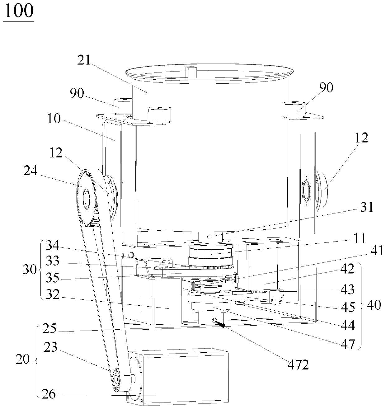
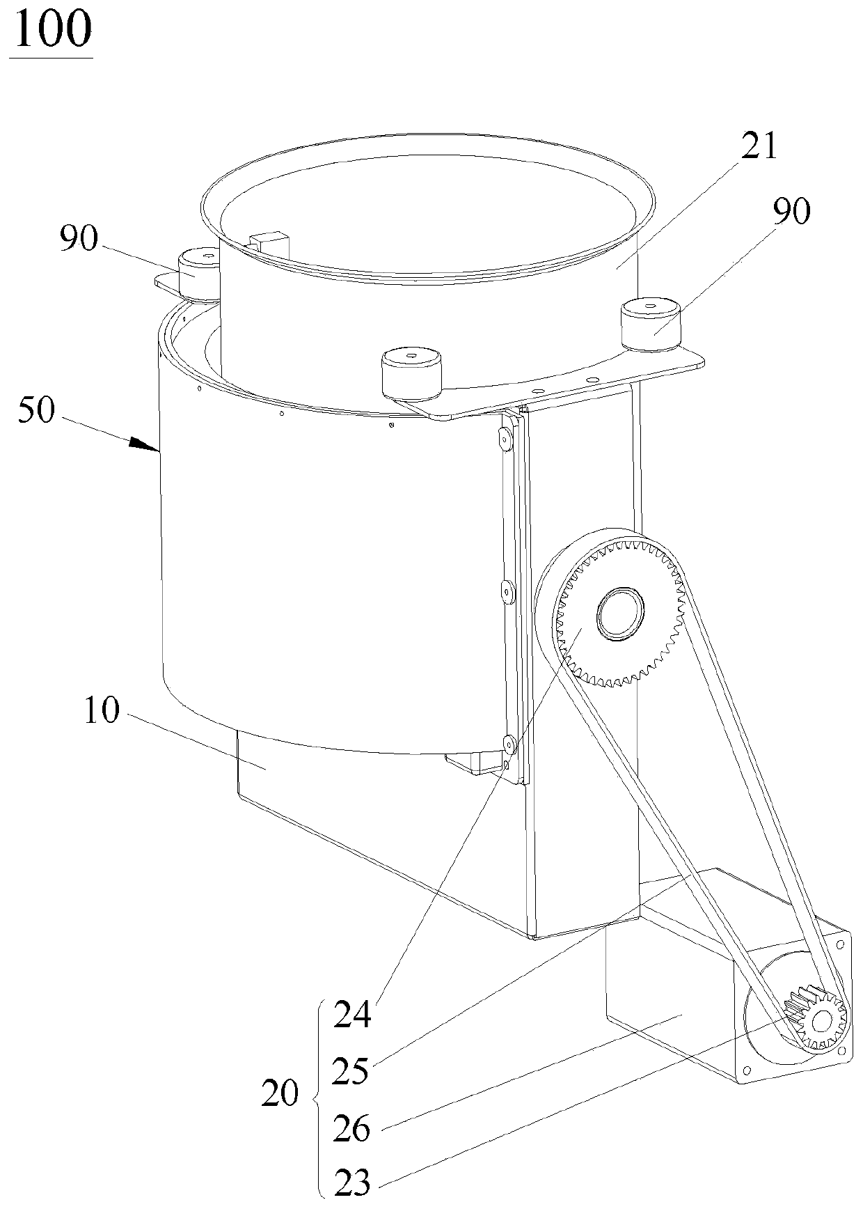
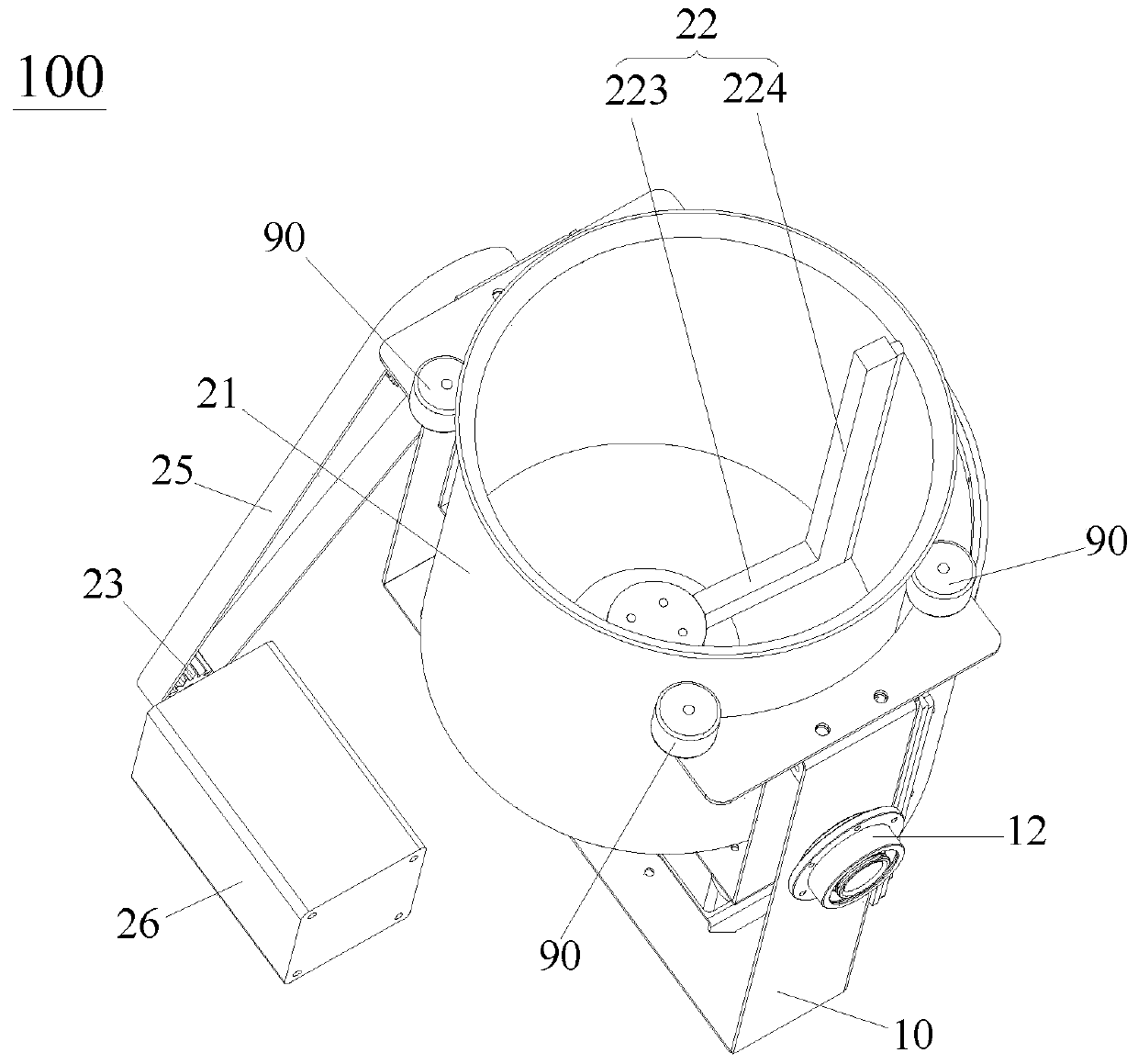
[0024] Such as Figure 1 to Figure 5 As shown, the automatic cooking machine 100 of the present invention includes a frame (not shown in the figure), a supporting bracket 10, a supporting member 11, a swing driving device 20, a pot body 21, a rotating driving device 30, a rotating shaft 31, a rotating The driving device 40, the rotating shaft 41, the heating device 50 and the stirring blade 22 located in the pot body 21, the supporting bracket 10 is pivotally installed on the frame, and the heating device 50 is installed on the supporting bracket 10 and surrounds the pot body 21, the input end of the swing driving device 20 is connected to the support bracket 10, the swing drive device 20 drives the support bracket 10 to reciprocate relative to the frame, the sup...


PUM


Abstract

The invention discloses an automatic cooker. The automatic cooker comprises a rack, a bearing frame, a bearing part, a swing driving device, a pot body, a rotation driving device, a rotation shaft, arotary driving device, a rotating shaft, a heating device and a stirring blade located in the pot body, wherein the bearing frame is pivotally mounted on the rack; the input end of the swing driving device is connected to the bearing frame; the heating device is mounted in the bearing frame and surrounds the outer side of the pot body; the bearing part is fixed on the bearing frame; the rotation shaft is rotationally mounted in the bearing part in a sleeving mode; the output end of the rotation driving device is connected to the first end of the rotation shaft; the second end of the rotation shaft is fixedly connected with the bottom of the pot body; the rotating shaft is rotatably arranged in the rotation shaft in a sleeving mode; the first end of the rotating shaft penetrates through thebottom wall of the pot body in the axial direction of the pot body and is assembled and connected with the stirring blade; and the output end of the rotary driving device is connected to the second end of the rotating shaft. The automatic cooker has three-axis input functions at the same time, and the structure of the automatic cooker is compact and optimized.

Description

technical field [0001] The invention relates to the field of kitchen cooking equipment, in particular to an automatic cooking machine. Background technique [0002] With the rapid development of social economy, in order to liberate the labor force, more and more automatic cooking machines are used in factories, campuses and restaurants. During the cooking process of the automatic cooking machine, whether it can fry delicious dishes mainly depends on the action of the pot body and the action of the stirring shovel. At the same time, how to make the materials be heated evenly and effectively without being fried has always been the field of automatic cooking equipment. The focus of attention, so this requires the automatic cooking machine to have good stir-frying skills. At present, the stir-frying technology can be generally divided into three types according to its realization method. Among them, one is to rely on the rotation of the pot body, which is characterized by a re...

Claims


Application Information

Patent Timeline
Patent Type & Authority Applications(China)
IPC IPC(8): A47J27/14A47J36/00A47J36/34A47J36/16
CPCA47J27/14A47J36/00A47J36/34A47J36/165
Inventor 王学勤
Owner 王学勤
Learn More