
Oil pump bracket assembly

A bracket assembly and oil pump technology, which is applied to engine components, liquid fuel feeders, machines/engines, etc., can solve problems such as poor robustness of the fixed form, difficult pressure control, component prolapse, etc., and achieve compact structure, optimization, and improved Vibration reduction effect, reliable and stable connection effect

Active Publication Date: 2017-03-22
UNITED AUTOMOTIVE ELECTRONICS SYST
View PDF7 Cites 0 Cited by
  • Summary
  • Abstract
  • Description
  • Claims
  • Application Information

AI Technical Summary

Problems solved by technology

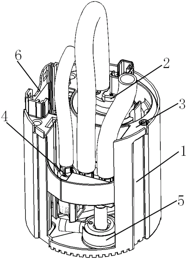
[0006] 3) The space occupied by the pressure regulating valve seat and the pipe joint assembly 4 in the oil storage barrel 1 is small, and the diaphragm type pressure regulating valve cannot be used, and only a small volume straight-through pressure regulating valve can be used, which makes the pressure difficult to control. At the same time, the fixing form of the pressure regulating valve seat and the pipe joint assembly 4 in the oil storage tank 1 is not robust enough, and the assembly is likely to come out after being impacted by the pipeline pressure;
[0007] 4) There is no buffer structure at the bottom of the oil storage barrel 1, and the vibration is relatively serious;
[0008] 5) The actively driven injection pump 5 and the oil storage tank 1 are connected by interference fit, which is non-elastic connection, has no buffer structure and poor assembly process

Method used


Image

  • Oil pump bracket assembly
  • Oil pump bracket assembly
  • Oil pump bracket assembly

Examples


Embodiment Construction

[0061] The present invention will be further described in detail below in conjunction with the accompanying drawings and specific embodiments.

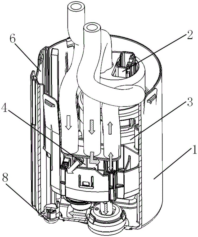
[0062] Oil pump bracket assembly of the present invention, as image 3 As shown, it includes an oil pump 2 located in an oil storage barrel 1, a guide rod 9 (not shown), a pressure regulating valve 10 and a collar 11 (not shown), a pressure regulating valve seat and a pipe joint assembly 4, and an oil pump bracket 3. Actively drive the injection pump 5, the sensor mounting seat 6, etc. In addition, the flow direction of the fuel in the oil circuit is involved image 3 and Figure 10 In , one type of arrow without a filling pattern indicates the oil return flow direction, and two kinds of arrows with a filling pattern indicate the oil outlet flow direction of the fuel pump and the fuel flow direction of the active return injection pump.

[0063] The following will refer to Figure 4 to Figure 13 Describe the structure and interconne...


PUM


Abstract

The invention discloses an oil pump rack assembly comprising an oil pump, a guide rod, a jetting pump, a pressure adjusting valve, a clamping ring, a pressure adjusting valve seat, a pipe fitting assembly, an oil pump support, an active-drive jetting pump and a sensor mounting seat. The oil pump and the guide rod are mounted on the oil pump support, the pressure adjusting valve is mounted in the pressure adjusting valve seat, the pressure adjusting valve seat and the pipe fitting assembly are fixedly connected with the oil pump support mounted on an oil barrel, the active-drive jetting pump is connected to one pipeline of the pipe fitting assembly in a sealed manner and is mounted in the oil barrel through a seal bowl, the sensor mounting seat is mounted on the oil barrel, and the bottom of the oil barrel is provided with a damping pad. According to the oil pump rack assembly, the sensor mounting seat is arranged on the oil barrel, the edge of the oil barrel can be lifted, and the volume of the oil barrel can be increased; the oil support integrates the oil pump, the pressure adjusting valve seat, the pipe fitting assembly and the jetting pump assembly, and assembly is facilitated; damping effect is improved, connections among components are more reliable and stable, and structure is more compact; and the system pressure can be more stable by the aid of the diaphragm type pressure adjusting valve.

Description

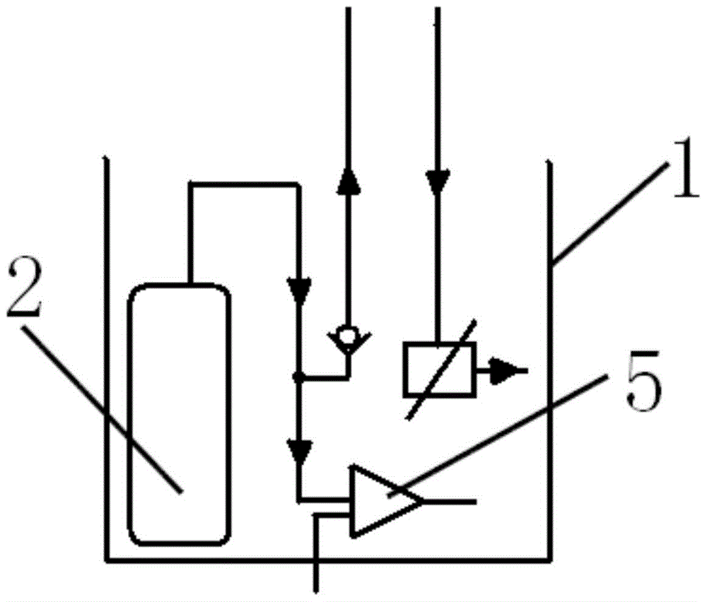
technical field [0001] The invention relates to a fuel supply device for a vehicle, in particular to an oil pump support assembly for active oil return. Background technique [0002] Due to the cramped structure of the existing support structure of the active oil return oil pump, there are few vibration damping mechanisms for the oil pump, and the capacity of the oil storage tank is small. figure 1 Shown is the structure of an existing oil pump bracket assembly in the form of active oil return, figure 2 is its schematic diagram. The oil pump bracket assembly includes an oil storage barrel 1, an oil pump 2, an oil pump bracket 3, a pressure regulating valve seat and a pipe joint assembly 4, an active drive jet pump 5 and a sensor mounting seat 6, wherein the oil pump 2, the oil pump bracket 3, the regulator The pressure valve seat, the pipe joint assembly 4, and the actively driven jet pump 5 are all located inside the oil storage barrel 1. The oil storage barrel 1 is loc...

Claims


Application Information

Patent Timeline
Patent Type & Authority Patents(China)
IPC IPC(8): F02M37/04
Inventor 徐巍巍郜业猛王子刚
Owner UNITED AUTOMOTIVE ELECTRONICS SYST
Learn More