Machining difference position compensation rounding method

A mechanical processing and differential technology, which is applied in the field of machining equipment, can solve the problems of low precision and low work efficiency, and achieve the effects of ensuring precision, saving manpower and material resources, and improving efficiency and precision

Active Publication Date: 2020-01-31
苏州荣倍合真空科技有限公司
View PDF6 Cites 1 Cited by
  • Summary
  • Abstract
  • Description
  • Claims
  • Application Information

AI Technical Summary

Problems solved by technology

[0003] Using manual repair, the work efficiency is relatively low, and the accuracy of the repair is lower th

Method used


Image

  • Machining difference position compensation rounding method
  • Machining difference position compensation rounding method
  • Machining difference position compensation rounding method

Examples


Example Embodiment

[0047] A specific embodiment of the present invention will be described in detail below in conjunction with the accompanying drawings, but it should be understood that the protection scope of the present invention is not limited by the specific embodiment.

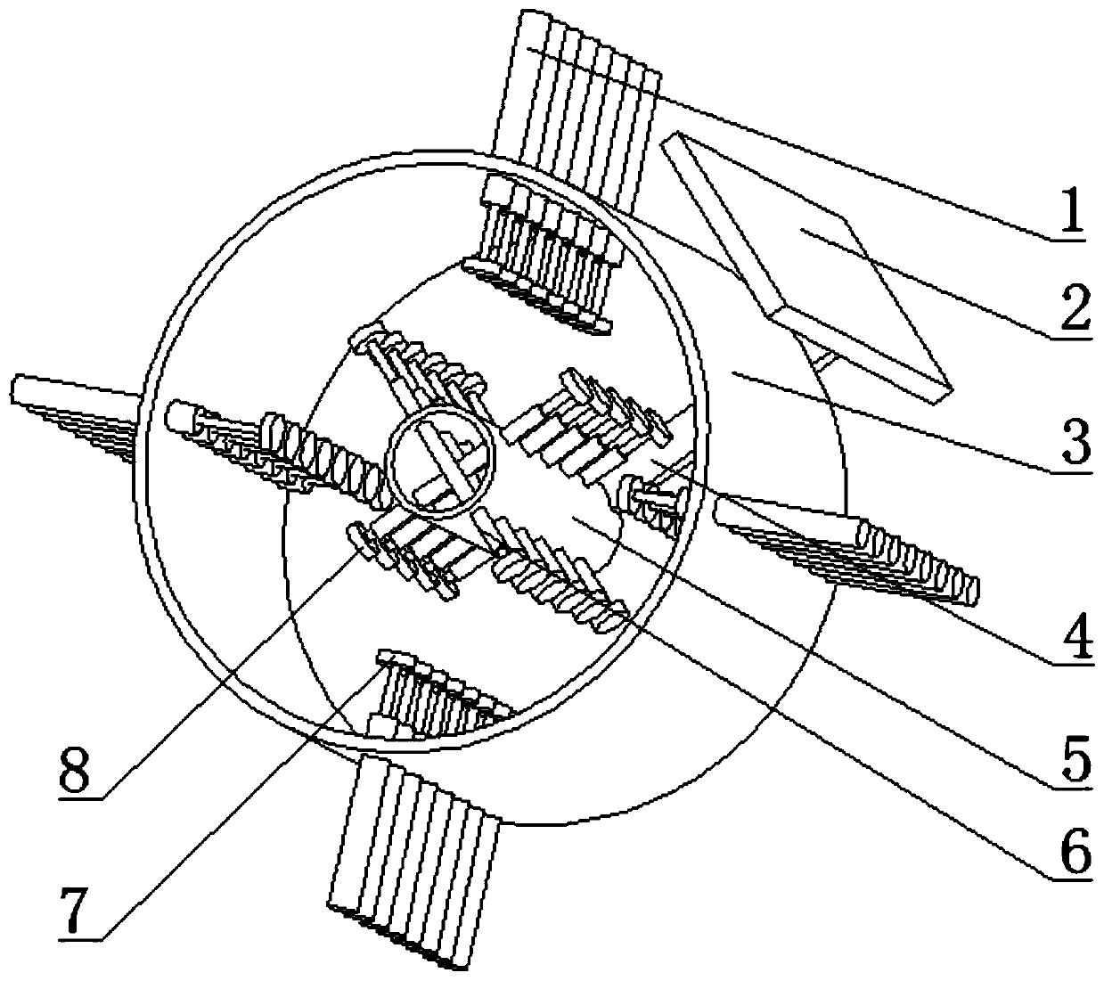
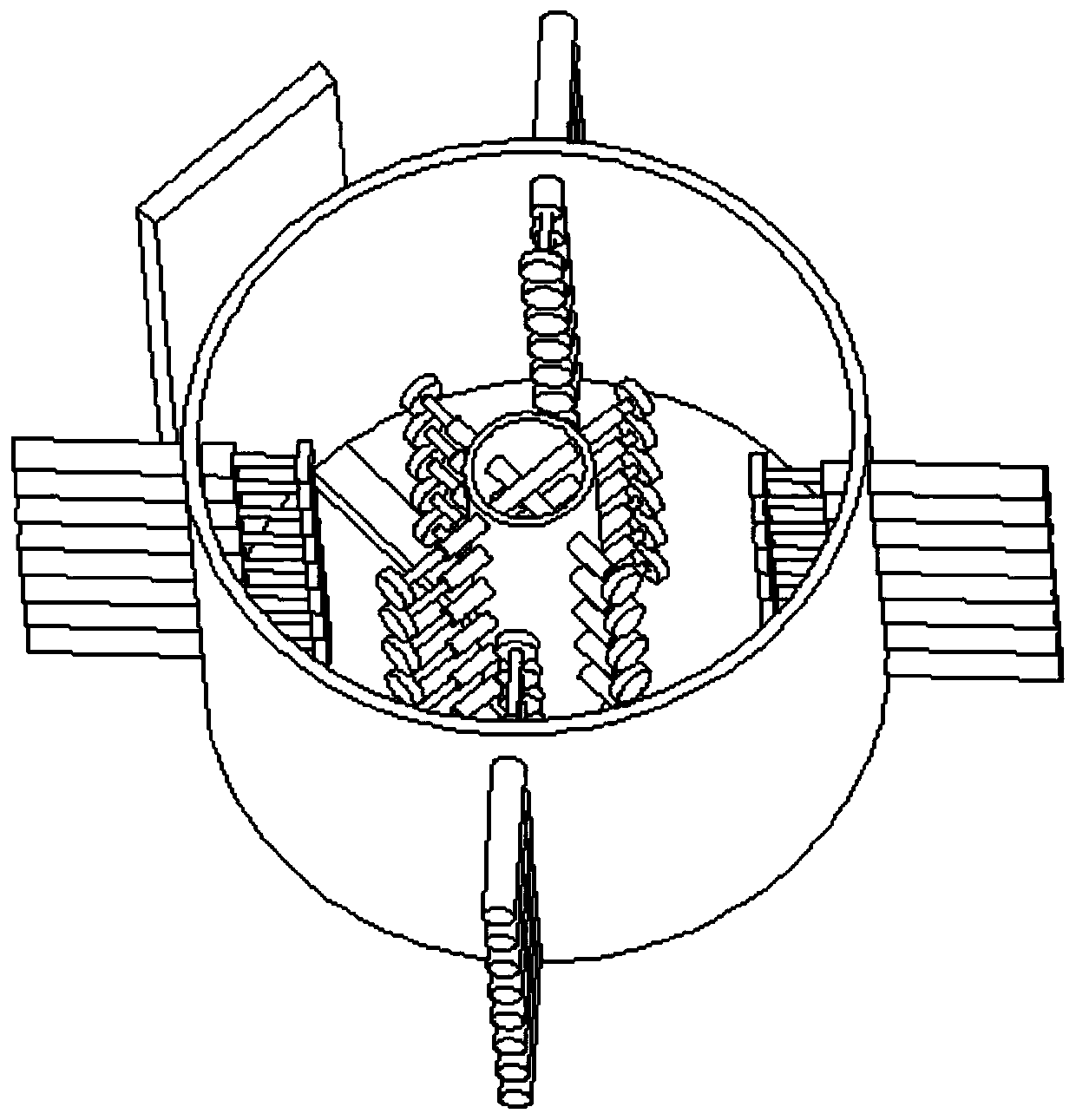
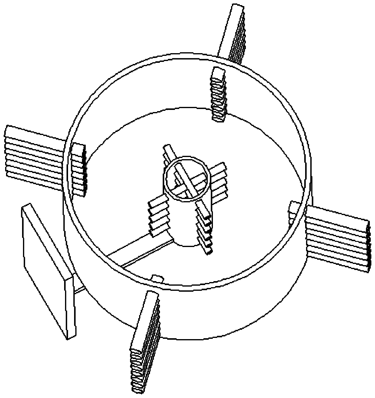
[0048] like Figure 1-Figure 3 As shown, the present invention includes a mounting base 2, the mounting base 2 is fixedly connected to one end of the horizontal plate 4, the middle part of the horizontal plate 4 is fixedly connected to the lower end of the outer cylinder 3, and the upper side of the other end of the horizontal plate 4 is fixed Connect the inner cylinder 5, the outer cylinder 3 is fixedly connected with a group of electric push rods 1 evenly distributed along the direction of the circular axis, and the inner cylinder 5 is fixedly connected with a group of electric push rods 2 evenly distributed along the direction of the circular axis 6. The push rod end of each electric push rod one 1 is fixedly connected ...


PUM


Abstract

The invention discloses a machining difference position compensation rounding method. A device adopted in the machining difference position compensation rounding method comprises an installing base and is characterized in that the installing base is fixedly connected with one end of a transverse plate, the middle of the transverse plate is fixedly connected with the lower end of an outer cylinder,the upper side of the other end of the transverse plate is fixedly connected with an inner cylinder, the outer cylinder is fixedly connected with a group of first electric pushing rods which are evenly distributed in the circular shaft direction, the inner cylinder is fixedly connected with a group of second electric pushing rods which are evenly distributed in the circular shaft direction, the pushing rod end of each first electric pushing rod is fixedly connected with a first rubber circular block, and the pushing rod end of each second electric pushing rod is fixedly connected with a second rubber circular block. The invention relates to the field of machining equipment, and particularly relates to the machining difference position compensation rounding method. According to the machining difference position compensation rounding method, cylindrical part repairing is convenient.

Description

technical field [0001] The invention relates to the field of machining equipment, in particular, to a method for compensating and rounding a machining position difference. Background technique [0002] Circular parts play an important role in industrial production. Circular parts are often used in some equipment, such as bushings, hollow shafts and hollow rods. Due to the harsh working environment of some equipment, these parts will be subject to various damages. After the circular parts are damaged, it is difficult to repair and mainly rely on manual repair. [0003] The manual repair method has low work efficiency, and the repaired accuracy is lower than that of the original product. At present, there is no specialized equipment for repairing circular parts. This is, the weak point of prior art. Contents of the invention [0004] The technical problem to be solved by the present invention is to provide a machining difference compensation rounding method to facilitate...

Claims


Application Information

Patent Timeline
IPC IPC(8): B23P6/00B23Q3/06
CPCB23P6/00B23Q3/065
Inventor 不公告发明人
Owner 苏州荣倍合真空科技有限公司
Why Eureka
Try Eureka