
Automatic cutting machine for fiber yarns

A fiber filament and cutting machine technology, which is used in the transportation of filamentous materials, metal processing, thin material processing, etc., can solve the problems of waste, loss of fiber filaments, time-consuming and laborious, so as to protect physical and mental health and reduce contact opportunities. , the effect of improving production efficiency

Pending Publication Date: 2020-01-31
ZHONGSHAN ZHENDEMEI PRECISION MASCH CO LTD
View PDF0 Cites 2 Cited by
  • Summary
  • Abstract
  • Description
  • Claims
  • Application Information

AI Technical Summary

Problems solved by technology

[0003] Therefore, the traditional winding method has the following disadvantages: 1. The length of the fiber is fixed and cannot be set flexibly and freely; 2. When fibers of different lengths are required, the corresponding winding wheel must be replaced, and the operation is time-consuming and laborious. It is not conducive to improving production efficiency; 3. For the operators, each shredding and wheel changing operation greatly increases the probability of contacting the residual film liquid, which is not conducive to the physical and mental health of the workers; 4. The winding method adopts manual cutting During the cutting process, part of the fiber will inevitably be lost, resulting in waste

Method used


Image

  • Automatic cutting machine for fiber yarns
  • Automatic cutting machine for fiber yarns
  • Automatic cutting machine for fiber yarns

Examples


Embodiment Construction

[0025] The present invention will be further described below in conjunction with specific examples.

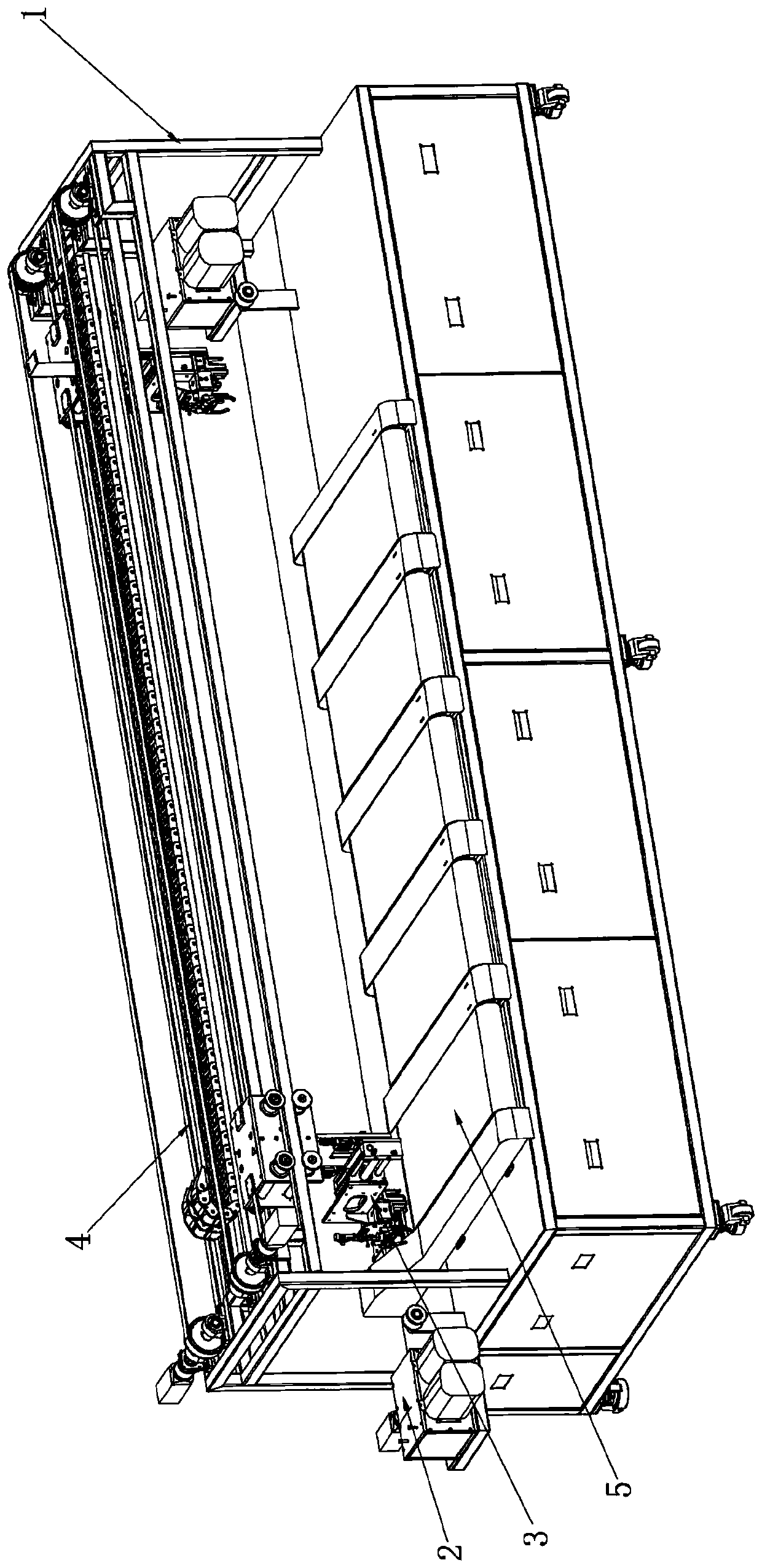
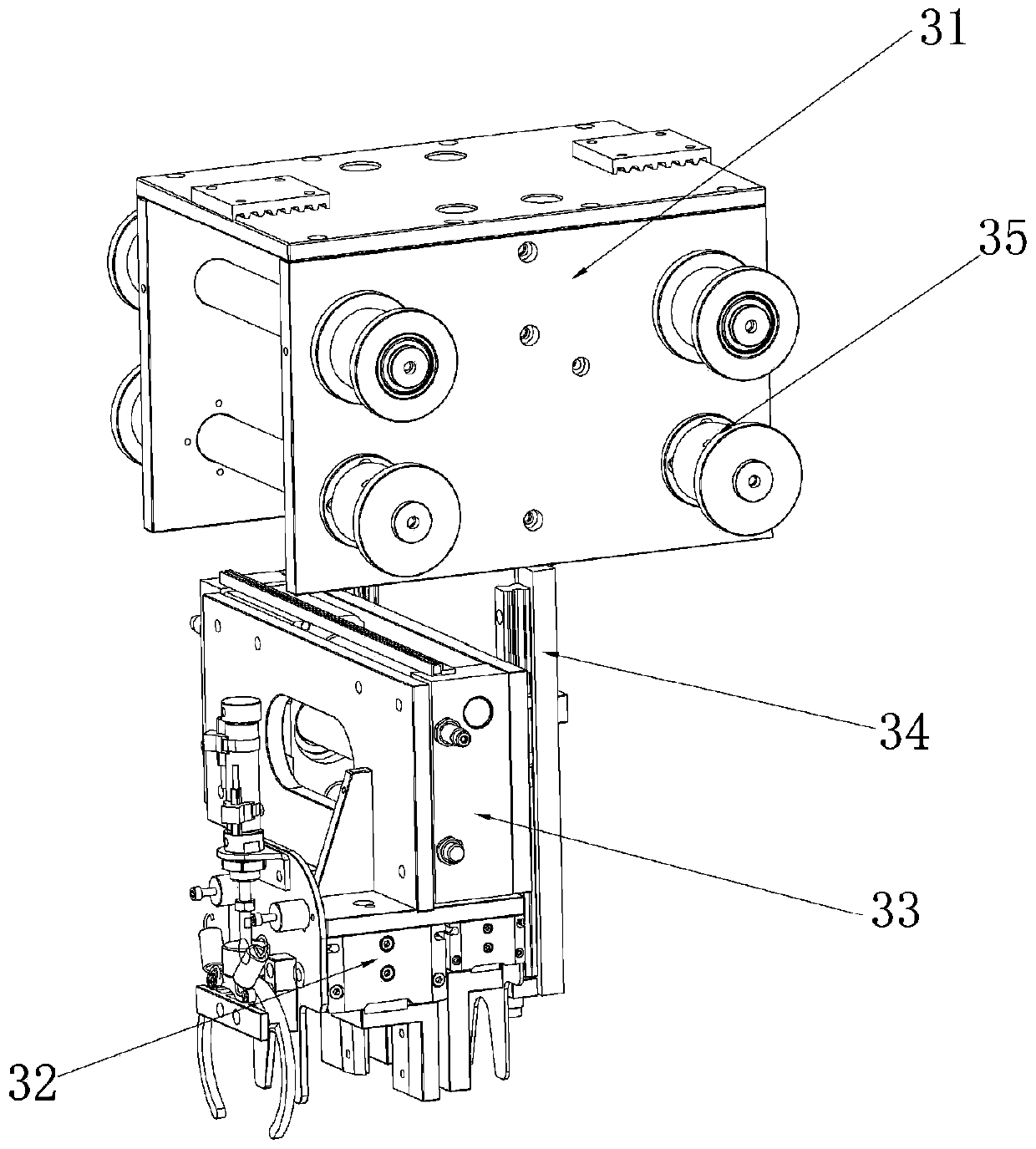
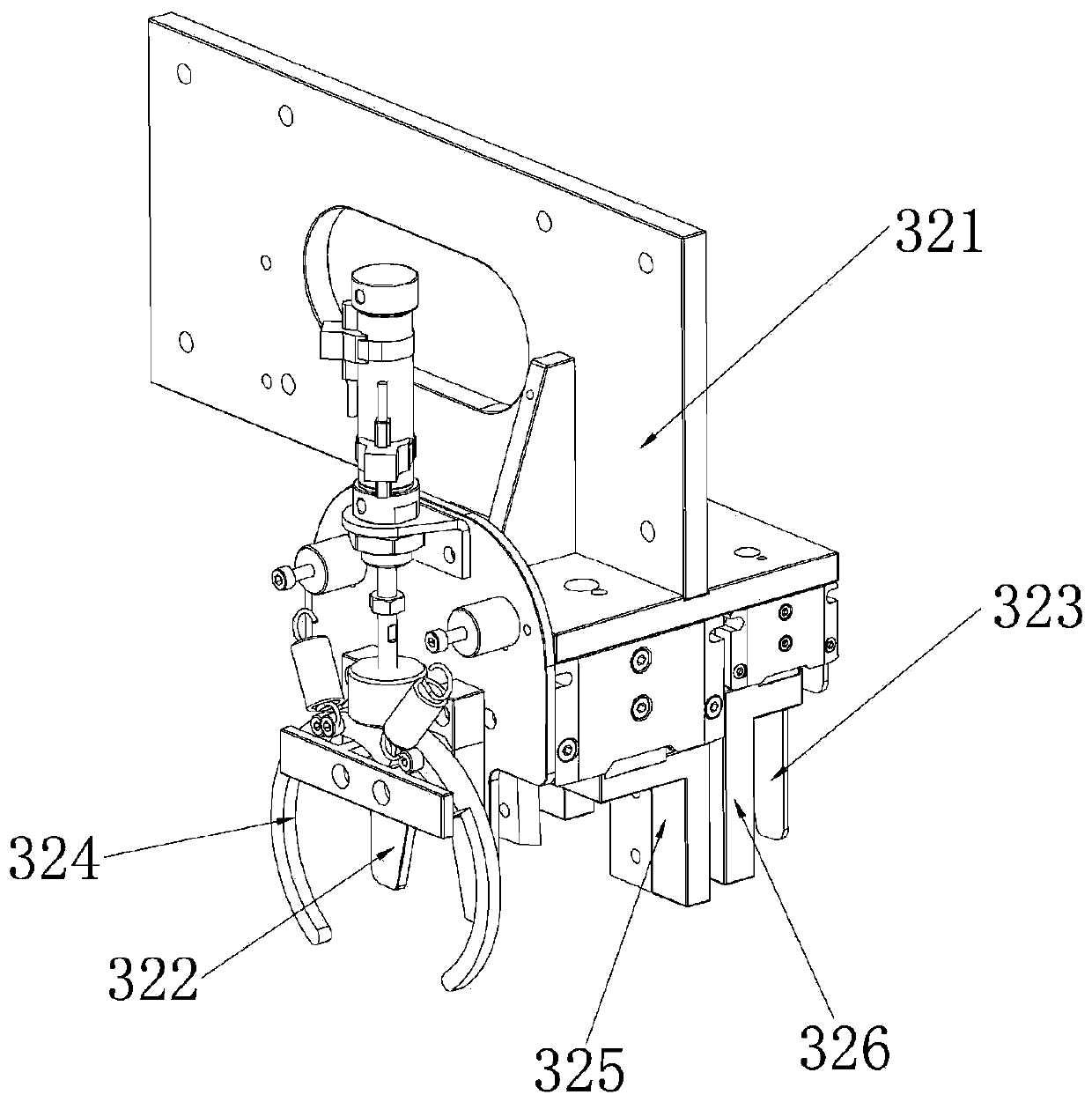
[0026] Such as figure 1 As shown, the fiber filament automatic cutting machine described in this embodiment includes a frame 1 and a feeding device 2, a manipulator 3, a reciprocating mechanism 4 and a conveying mechanism 5 arranged on the frame 1; the feeding device 2 has Two, respectively located at the front and rear ends of the frame 1, the fiber filaments are conveyed from the feeding device 2 at the rear end to the feeding device 2 at the front end, and the speed of the two feeding devices 2 conveying the fiber filaments is related to the fiber spinning The spinning speed of the machine matches the spinning speed; there are two manipulators 3, which slide on two parallel guide rails of the frame 1, and are located between the two feeding devices 2, and each manipulator 3 is connected with a reciprocating The motion mechanism 4, two reciprocating mechanisms 4 are paralle...


PUM


Abstract

The invention discloses an automatic cutting machine for fiber yarns. The automatic cutting machine comprises a machine frame, two feeding devices, two manipulators and reciprocating mechanisms, wherein the feeding devices, the manipulators and the reciprocating mechanisms are arranged on the machine frame. The two feeding mechanisms are separately arranged at the front end and the rear end of themachine frame. The fiber yarns are conveyed from the feeding device at the rear end to the feeding device at the front end, and the fiber yarn conveying speed of the two feeding devices is matched with the spinning speed of a fiber spinning machine. The two manipulators are slidably arranged on two parallel guide rails of the machine frame correspondingly and are located between the two feeding devices. The upper portion of each manipulator is connected with one reciprocating mechanism, and the two reciprocating mechanisms are arranged in parallel. The two manipulators are driven by the corresponding reciprocating mechanisms to reciprocate alternately to grab and cut the fiber yarns. According to the automatic cutting machine, the cutting length of the fiber yarns can be selected according to requirements without stopping the spinning machine, and cutting and automatic collection of the fiber yarns are achieved.

Description

technical field [0001] The invention relates to the technical field of on-line automatic fiber cutting by a spinning machine, in particular to an automatic fiber cutting machine. Background technique [0002] At present, in enterprises producing hollow fiber membranes or chemical fibers (hereinafter collectively referred to as fibers), basically a set of (two wheels) winding wheels are used for winding hollow fiber membranes or chemical fibers. The fiber is wound on the surface of the wheel through the rotation of the winding wheel itself. When a winding wheel is wound up to a certain amount, the worker needs to manually wind the fiber being spun to another empty wheel to continue winding. , and then use the blade to cut off the fiber filaments on the wheel along the generatrix direction of the wheel, so that the entire length of the bundle is fixed to a certain number of fiber filament bundles. Since the fiber is wound on the surface of the take-up wheel through the rotati...

Claims


Application Information

Patent Timeline
Patent Type & Authority Applications(China)
IPC IPC(8): B26D7/02B26D1/09B26D5/12B65H51/18
CPCB26D1/09B26D5/12B26D7/02B65H51/18
Inventor 魏祖林许志鹏唐帅
Owner ZHONGSHAN ZHENDEMEI PRECISION MASCH CO LTD
Learn More