
Exhaust device of motorcycle, engine exhaust system and motorcycle

A technology for exhaust devices and motorcycles, which is applied in the direction of exhaust devices, engine components, machines/engines, etc., which can solve the problems of long exhaust paths and achieve the effect of improving exhaust purification performance

Active Publication Date: 2020-01-31
SUZUKI MOTOR CORP
View PDF9 Cites 0 Cited by
  • Summary
  • Abstract
  • Description
  • Claims
  • Application Information

AI Technical Summary

Problems solved by technology

[0010] In addition, in the case of a multi-cylinder engine, the exhaust path to the catalyst body tends to be longer because the catalyst body is arranged in the manifold or behind the manifold.

Method used


Image

  • Exhaust device of motorcycle, engine exhaust system and motorcycle
  • Exhaust device of motorcycle, engine exhaust system and motorcycle
  • Exhaust device of motorcycle, engine exhaust system and motorcycle

Examples


Embodiment Construction

[0024] Embodiments of the present invention will be described below based on the drawings.

[0025] In the following embodiments, an example in which the motorcycle exhaust device according to the present invention is applied to a two-cylinder motorcycle will be described, but the vehicle type is not limited thereto. For example, this exhaust device can also be applied to a multi-cylinder engine such as a four-cylinder or a single cylinder. In addition, the exhaust device can also be applied to vehicles such as a three-wheeled vehicle, a four-wheeled vehicle, or a snowmobile other than motorcycles.

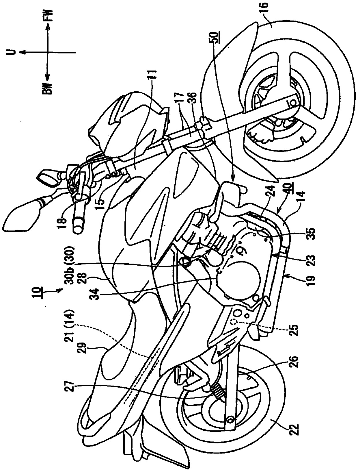
[0026] In addition, in the following embodiments, the indications of up and down, left and right, and front and rear are based on the driver (rider) when the vehicle is riding. In each figure, the vehicle front is indicated by arrow FW, the vehicle rear is indicated by arrow BW, the vehicle left direction is indicated by arrow L, the vehicle right direction is indicated by arrow ...


PUM


Abstract

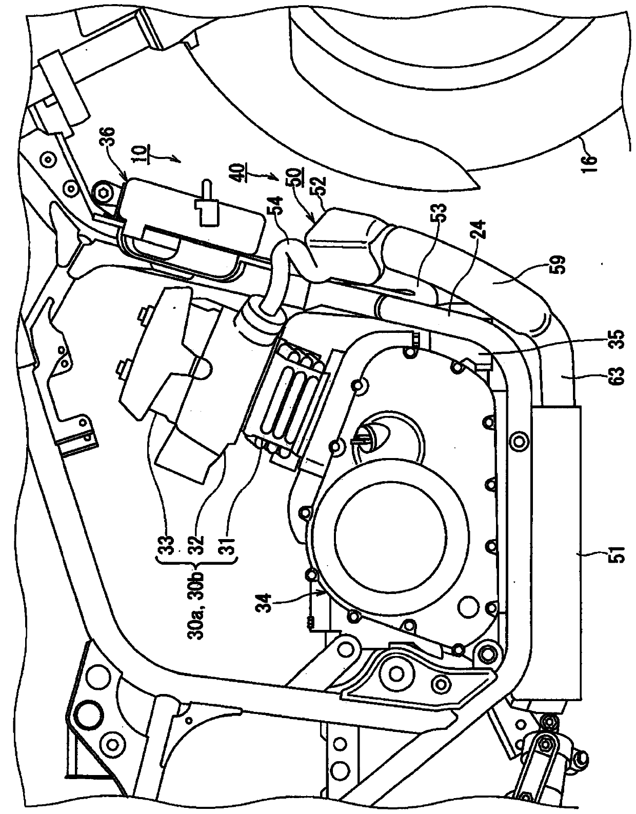
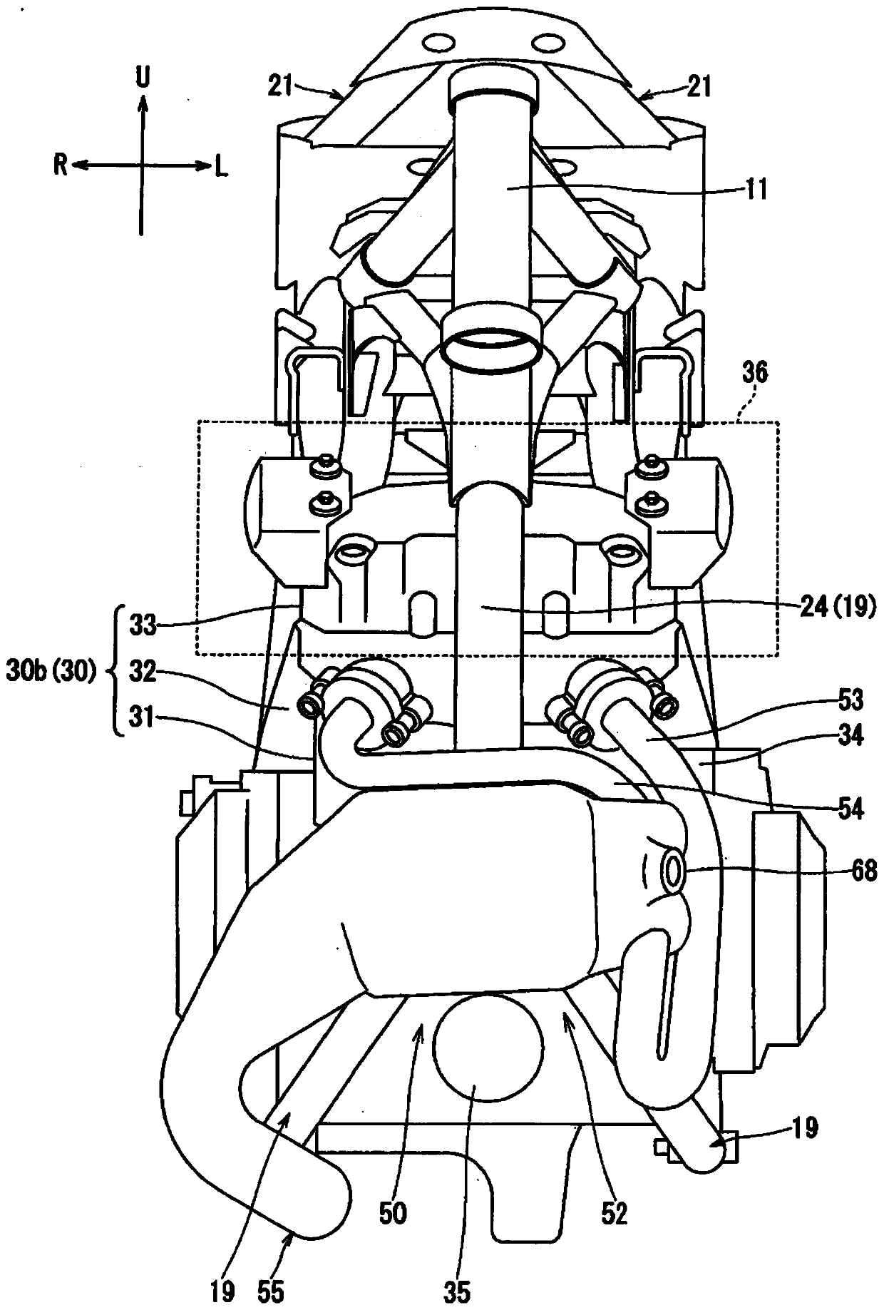
The invention provides an exhaust device of a motorcycle, an engine exhaust system and the motorcycle, wherein the exhaust purification performance is improved by utilizing waste heat. The exhaust device (50) for a motorcycle is provided with: upstream-side exhaust pipes (53, 54) connected to an exhaust port of a cylinder head (32) of an engine (23); an inflow head chamber (57) connected to the ends of the upstream-side exhaust pipes (53, 54); a purge chamber (56) having an inlet opening to the inflow head chamber (57) and containing a catalyst body therein; and a downstream-side exhaust pipe(55) which is connected to the outflow side of the purge chamber (56), wherein a catalyst tank (52) having an inflow head chamber (57) and the purge chamber (56) is disposed in front of and below thecylinder head (32) and above the lower end of a crankcase (34).

Description

technical field [0001] Embodiments of the present invention relate to a motorcycle exhaust technology. Background technique [0002] Exhaust gas discharged from the cylinder head of the engine passes through an engine exhaust system connected to the cylinder head, becomes clean air, and is discharged toward the rear of the vehicle. [0003] Many types of engine exhaust systems are conventionally configured such that a muffler that is open to the atmosphere near the rear wheels is connected to an exhaust device that extends rearward from the cylinder head along the bottom of the engine. Exhaust gas is purified into clean air that can be discharged into the atmosphere while passing through the catalyst body housed in the exhaust device near the bottom of the engine or at the rear of the engine. [0004] When the engine is a multi-cylinder engine, an engine exhaust system of the type in which part or all of the exhaust pipes connected to the cylinders are combined by a manifol...

Claims


Application Information

Patent Timeline
Patent Type & Authority Applications(China)
IPC IPC(8): F01N13/08F01N3/28F01N3/20
CPCF01N13/08F01N3/28F01N3/2006Y02A50/20Y02T10/12
Inventor 村冈哲郎长谷川庆
Owner SUZUKI MOTOR CORP
Learn More