
Catalytic converter

A catalytic converter and carrier technology, applied in chemical instruments and methods, machines/engines, separation methods, etc., can solve the problems of reduced exhaust gas inflow, increased pressure loss of exhaust gas flow, and will not be easy

Inactive Publication Date: 2013-12-04
TOYOTA JIDOSHA KK +1
View PDF13 Cites 0 Cited by
  • Summary
  • Abstract
  • Description
  • Claims
  • Application Information

AI Technical Summary

Problems solved by technology

However, if Figure 7 As shown, if the central area of ​​the upstream catalyst where the exhaust gas that has entered the catalytic converter first flows into has a large cell density, the pressure loss with respect to the exhaust gas flow will increase
As a result, for Figure 7 With the catalytic converter shown, the exhaust will not flow easily, so the result may be a reduced inflow of exhaust

Method used


Image

  • Catalytic converter
  • Catalytic converter
  • Catalytic converter

Examples


Embodiment Construction

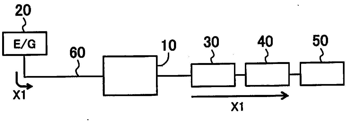
[0027] Hereinafter, exemplary embodiments of the catalytic converter of the present invention will be described with reference to the accompanying drawings. figure 1 is a diagram showing a frame form of an exhaust system for exhaust gas in which a catalytic converter according to an exemplary embodiment of the present invention is inserted.

[0028] The exhaust system for exhaust gas includes: an engine 20 , a catalytic converter 10 , a three-way catalytic converter 30 , an auxiliary muffler 40 and a main muffler 50 . The engine 20 and the catalytic converter 10 are connected by a system conduit 60 . Similarly, catalytic converter 10 is connected to three-way catalytic converter 30 , which is connected to auxiliary muffler 40 , and auxiliary muffler 40 is connected to main muffler 50 , all via system conduit 60 . That is, the engine 20 is connected to the upstream portion of the catalytic converter 10 via the system conduit 60 . Exhaust gas produced by the engine 20 at fi...


PUM

PropertyMeasurementUnit
diameteraaaaaaaaaa
lengthaaaaaaaaaa

Abstract

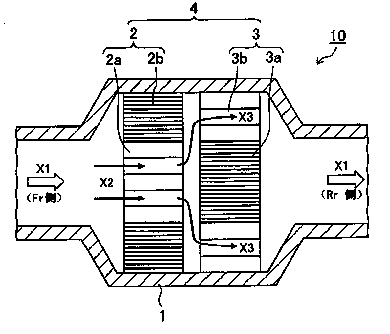
A catalytic converter (10) has a carrier (4) with a cell structure, and a precious metal catalyst carried on the carrier. The carrier includes a first carrier (2) and a second carrier (3). The second carrier is provided downstream of the first carrier in a gas flow direction of gas that flows into the catalytic converter. The first carrier has a first peripheral region (2b) and a first center region (2a) that has a lower cell density than the first peripheral region. The second carrier has a second center region (3a) and a second peripheral region (3b) that has a lower cell density than the second center region.

Description

technical field [0001] The invention relates to a catalytic converter arranged in a conduit forming an exhaust system for exhaust gas. Background technique [0002] In various industrial fields, various efforts are being made to reduce environmental impact on a global scale. Among them, in the automobile industry, in addition to the development of gasoline engine vehicles with sufficient fuel efficiency performance, so-called eco-cars (eco-friendly cars) such as hybrid cars and electric cars are also spreading and are being developed to further improve performance of these vehicles. [0003] Typically, a catalytic converter for purifying exhaust gas is arranged in an exhaust system for exhaust gas that connects a vehicle engine to a muffler. [0004] Engines emit harmful substances such as CO, NOx, unburned HC, and volatile organic compounds (VOCs) into the environment. These harmful substances are converted into acceptable substances by passing the exhaust gas through th...

Claims


Application Information

Patent Timeline
Patent Type & Authority Applications(China)
IPC IPC(8): F01N3/28
CPCB01D53/9477B01D53/94B01D2255/904B01D2255/9202
Inventor 铃木宏昌中野道晴垣花大松原浩之村田雅一林真大
Owner TOYOTA JIDOSHA KK
Learn More