
Valve-in-valve applied to zero power of turbine low pressure cylinder

A low-pressure cylinder and zero-power technology, which is applied in the direction of valve lift, valve details, valve devices, etc., can solve the problems of difficult linear adjustment of flow rate, difficulty in controlling flexible switching between extremely large flow and extremely small flow, etc.

Inactive Publication Date: 2020-01-31
润电能源科学技术有限公司
View PDF6 Cites 4 Cited by
  • Summary
  • Abstract
  • Description
  • Claims
  • Application Information

AI Technical Summary

Problems solved by technology

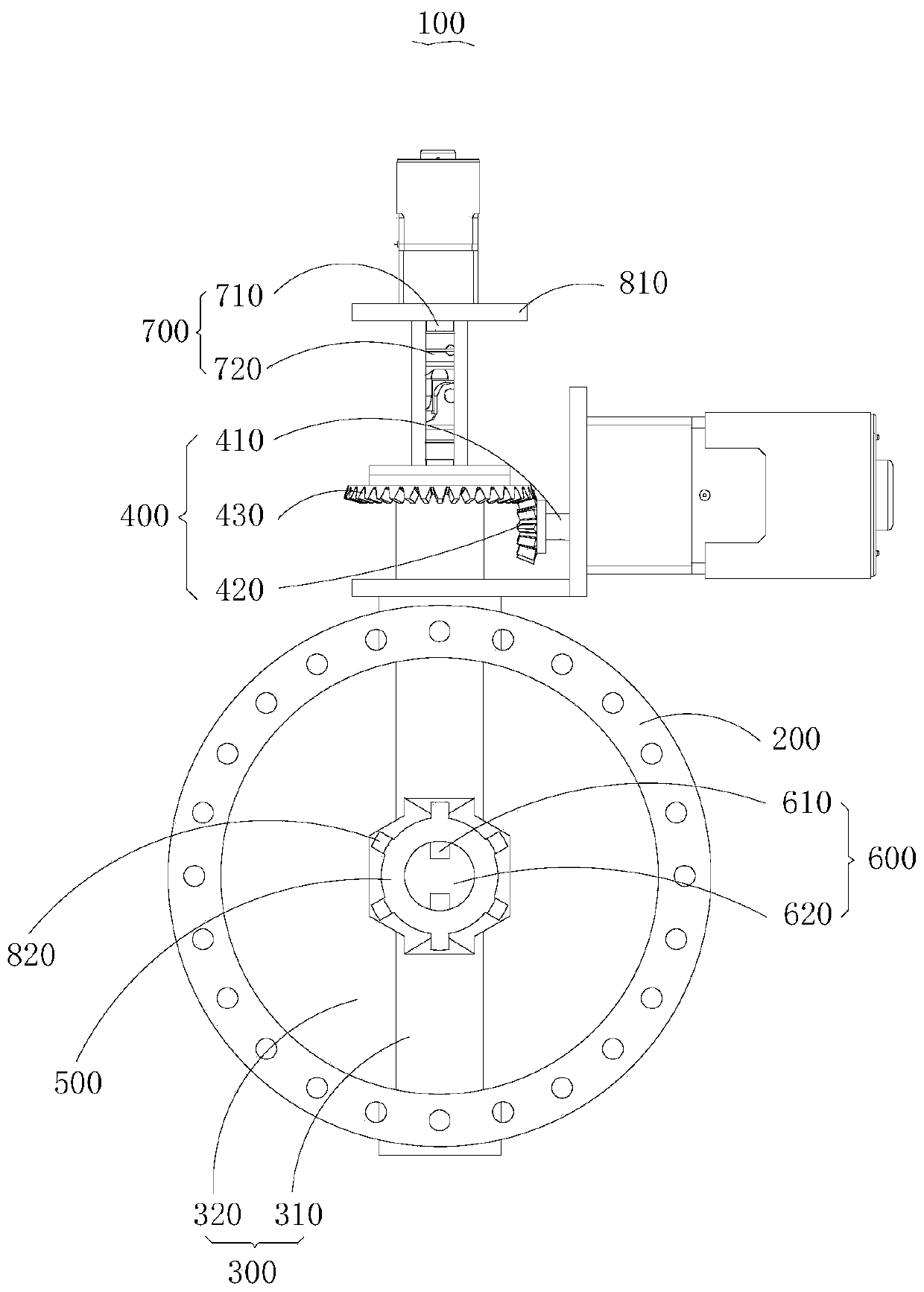
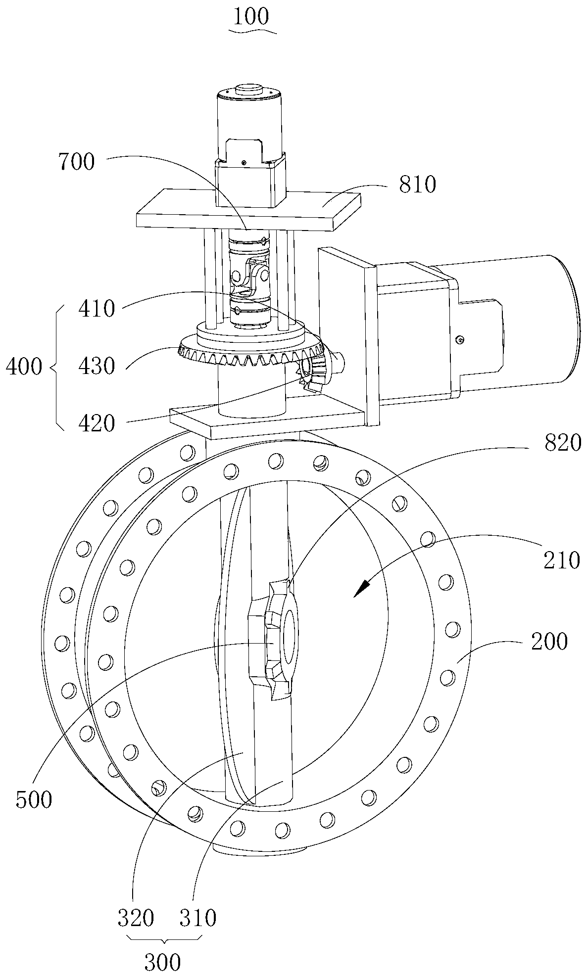
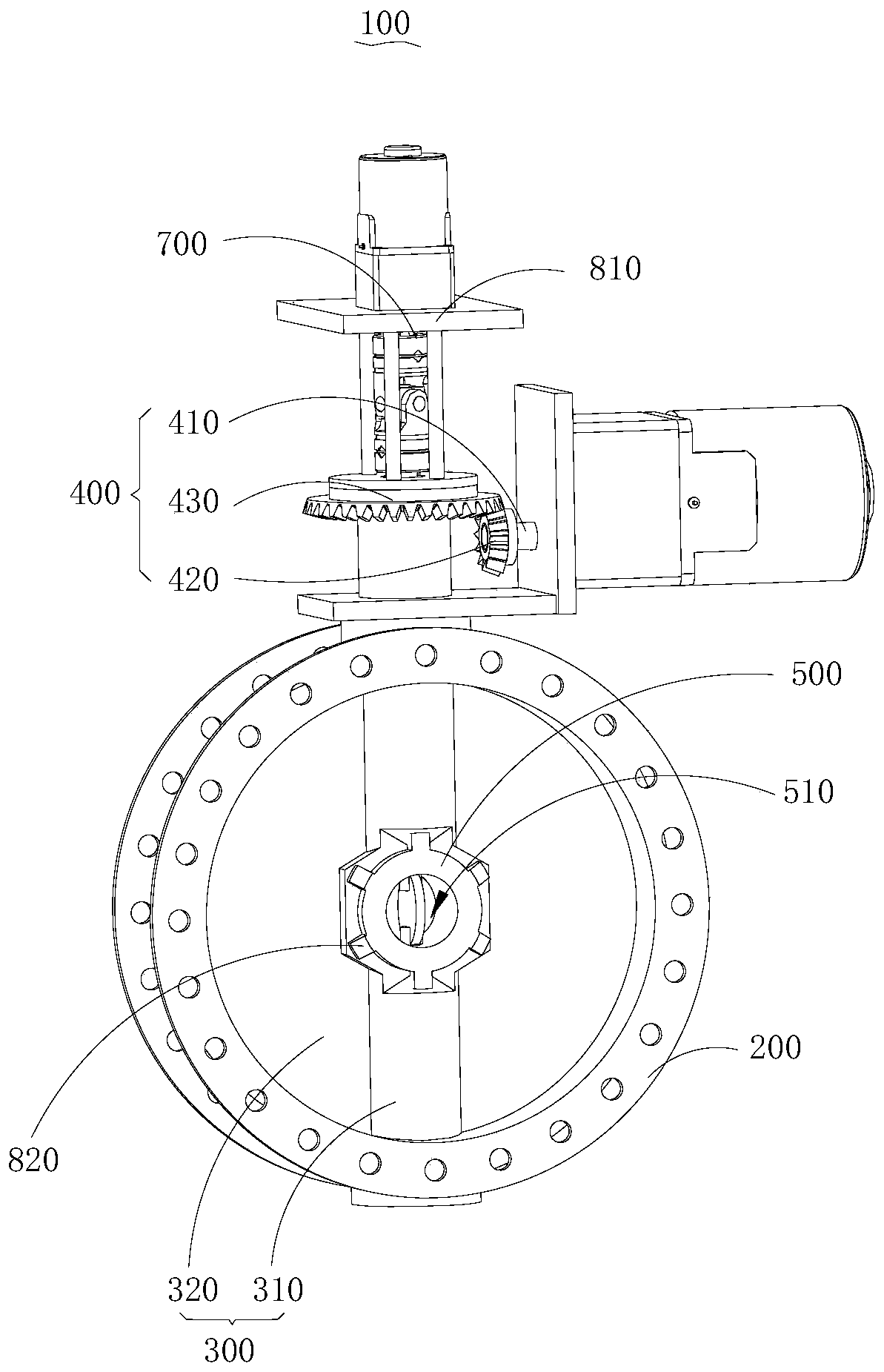
[0004] The main purpose of the present invention is to provide a valve-in-valve applied to the low-pressure cylinder of a steam turbine with zero power. The problem of flexible switching

Method used


Image

  • Valve-in-valve applied to zero power of turbine low pressure cylinder
  • Valve-in-valve applied to zero power of turbine low pressure cylinder
  • Valve-in-valve applied to zero power of turbine low pressure cylinder

Examples


Embodiment Construction

[0025] The following will clearly and completely describe the technical solutions in the embodiments of the present invention with reference to the accompanying drawings in the embodiments of the present invention. Obviously, the described embodiments are only part of the embodiments of the present invention, not all of them. Based on the embodiments of the present invention, all other embodiments obtained by persons of ordinary skill in the art without creative efforts fall within the protection scope of the present invention.

[0026] It should be noted that all directional indications (such as up, down, left, right, front, back...) in the embodiments of the present invention are only used to explain the relationship between the components in a certain posture (as shown in the accompanying drawings). Relative positional relationship, movement conditions, etc., if the specific posture changes, the directional indication will also change accordingly.

[0027] In addition, in t...


PUM


Abstract

The invention discloses a valve-in-valve applied to the zero power of a turbine low pressure cylinder. The valve-in-valve comprises a first valve seat, a first valve element, a first driving component, a second valve seat, a second valve element and a second driving component. A first circulating hole is formed in the first valve seat, the first valve element is arranged on the first valve seat, and the first driving component is connected with the first valve element in a transmission mode and is used for driving the first valve element to move to make the first valve element open or close the first circulating hole. The second valve seat is arranged on the first valve element, a second circulating hole is formed in the second valve seat, the second valve element is arranged on the secondvalve seat, and the second driving component is connected with the second valve element in a transmission mode and used for driving the second valve element to make the second valve element to open or close the second circulating hole. The first circulating hole is used for carrying out linear mediation on circulation of maximum discharge, the second circulating hole is used for carrying out linear regulation on minimum discharge, and flexible switching of the maximum discharge and the minimum discharge is achieved through alternative opening of the first circulating hole and the second circulating hole.

Description

technical field [0001] The invention relates to the technical field of regulating valves, in particular to a valve-in-valve applied to a zero-power low-pressure cylinder of a steam turbine. Background technique [0002] Regulating valves are used in power generation and heating equipment, and the flow into the low-pressure cylinder is controlled by setting a regulating valve between the medium-pressure cylinder and the low-pressure cylinder. During the non-heating period, the flow rate entering the low-pressure cylinder through the regulating valve is extremely large, which meets the needs of power generation; The value is more than twenty times different from the minimum value. However, in terms of small flow control, the existing control valves are difficult to achieve linear adjustment of extremely small flow and flexible switching between the limit flow of the flow entering the low-pressure cylinder. [0003] Therefore, it is necessary to provide a new valve-in-valve a...

Claims


Application Information

Patent Timeline
Patent Type & Authority Applications(China)
IPC IPC(8): F16K1/22F16K1/32F16K1/52F16K27/02F16K31/53F16K31/54F16K31/44F01D17/14
CPCF01D17/145F16K1/221F16K1/223F16K1/32F16K1/52F16K27/0218F16K31/44F16K31/535F16K31/54
Inventor 卢允谦张清甫
Owner 润电能源科学技术有限公司
Learn More