
Self-locking type liquid driving type ball valve

A driving and self-locking technology, which is applied to the valve details, valve device, valve housing structure, etc., can solve the problems of non-replacement, troublesome operation, and failure to prevent the interface, so as to prevent the interface from leaking, use the effect well, and reduce losses. Effect

Inactive Publication Date: 2020-01-31
NANTONG LONGYUAN POWER STATION VALVE
View PDF8 Cites 0 Cited by
  • Summary
  • Abstract
  • Description
  • Claims
  • Application Information

AI Technical Summary

Problems solved by technology

[0002] The valve is a pipeline accessory used to open and close the pipeline, control the flow direction, adjust and control the parameters of the conveying medium, and is a control component in the fluid conveying system. Functions such as flow and pressure relief; the existing valves have certain disadvantages in use. First, it cannot be easily replaced after the adjustment handle is damaged, and the loss caused by the damage of the handle cannot be reduced. Secondly, the interface cannot be effectively prevented during the use of the valve. Water leakage makes it impossible to quickly disassemble and replace parts when a fault occurs inside the valve. Finally, the valve cannot withstand high pressure during use, and the water delivery port is prone to water seepage. To this end, we propose a self-locking liquid-actuated ball valve

Method used


Image

  • Self-locking type liquid driving type ball valve
  • Self-locking type liquid driving type ball valve
  • Self-locking type liquid driving type ball valve

Examples


Embodiment Construction

[0017] In order to make the technical means, creative features, goals and effects achieved by the present invention easy to understand, the present invention will be further described below in conjunction with specific embodiments.

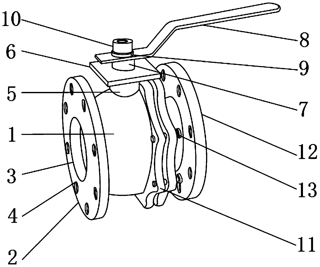
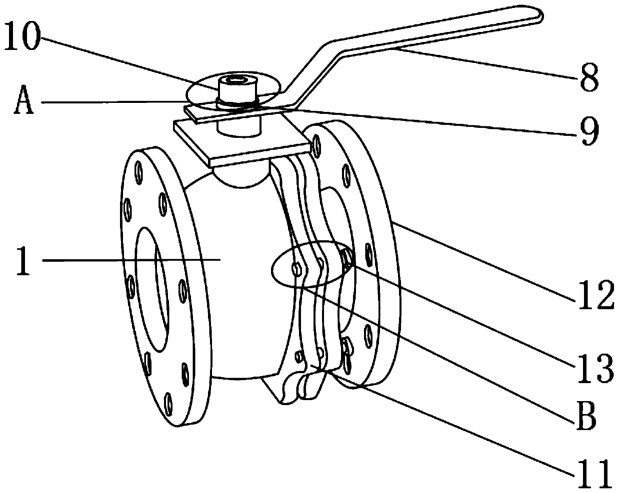
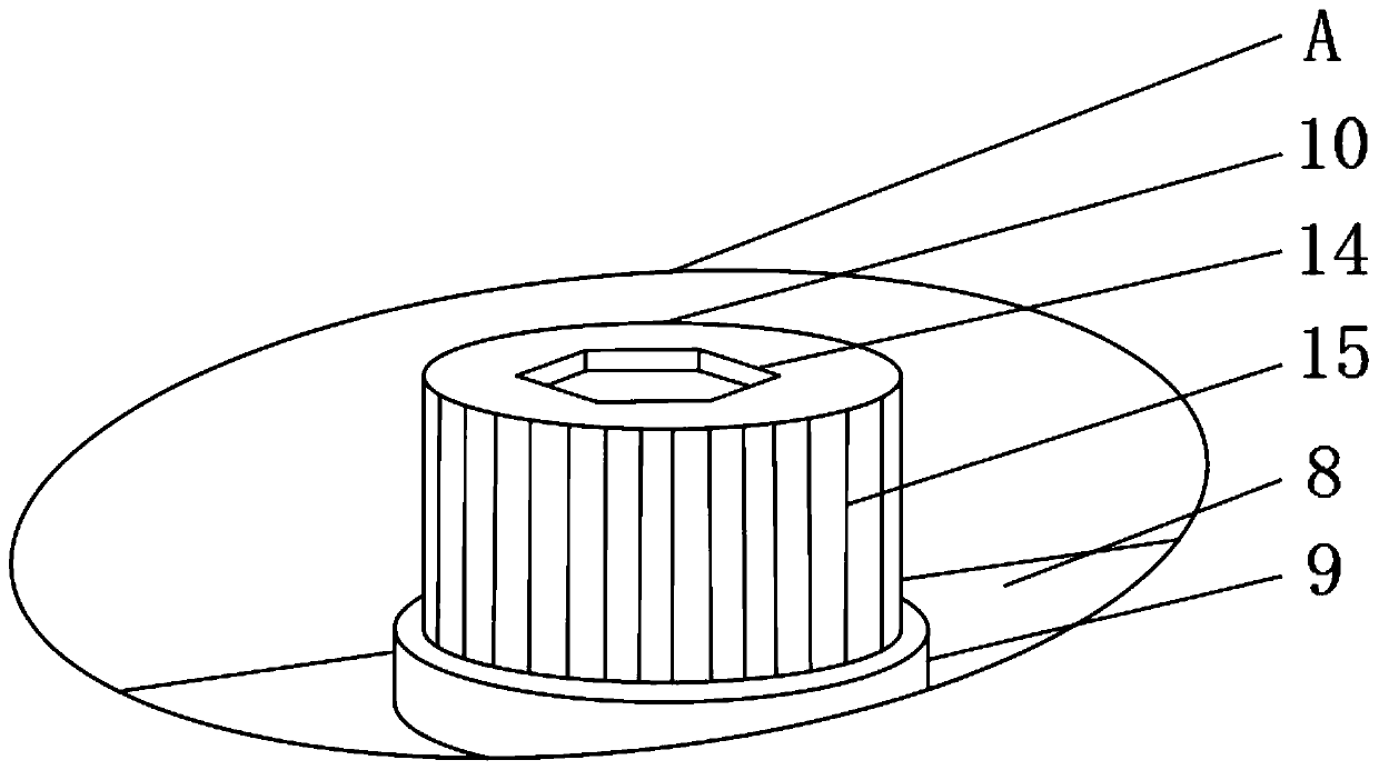
[0018] Such as Figure 1-4 As shown, a self-locking liquid-driven ball valve includes a main body pipe 1, a No. 1 flange 2 is fixedly installed on one side of the outer surface of the main body 1, and a No. The water delivery port 3 is provided with a screw hole 4 around the water delivery port 3, and the screw hole 4 is fixedly installed on the outer surface of one side of the No. 1 flange 2, and a connecting pipe 5 is fixedly installed in the center of the outer surface of the upper end of the main pipe 1. The outer surface of the upper end of the connecting pipe 5 is fixedly installed with a fixed platform 6, and the center of the outer surface of the upper end of the fixed platform 6 is fixedly installed with a connecting shaft 7. The outer su...


PUM


Abstract

The invention discloses a self-locking type liquid driving type ball valve. The self-locking type liquid driving type ball valve comprises a main body pipe; a first flange plate is fixedly arranged onthe outer surface of one side of the main body pipe; a water delivery port is fixedly arranged in the center of the outer surface of one side of the first flange plate; screw holes are formed in theperiphery of the water delivery port; the screw holes are fixedly arranged on the outer surface of one side of the first flange plate; a connecting pipe is fixedly arranged in the center of the outersurface of the upper end of the main body pipe; a fixed table is fixedly arranged on the outer surface of the upper end of the connecting pipe; and a connecting shaft is fixedly arranged at the centerof the outer surface of the upper end of the fixed table. According to the self-locking type liquid driving type ball valve, a movable bolt, a connecting plate and a second flange plate are arranged,the ball valve can be conveniently replaced after an adjusting handle is damaged, the water leakage of a connector can be prevented in the use process of a valve, and the large pressure can be bornewhen the valve is used, and the better use prospect is brought.

Description

technical field [0001] The invention relates to the field of valves, in particular to a self-locking liquid-driven ball valve. Background technique [0002] The valve is a pipeline accessory used to open and close the pipeline, control the flow direction, adjust and control the parameters of the conveying medium, and is a control component in the fluid conveying system. Functions such as flow and pressure relief; the existing valves have certain disadvantages in use. First, it cannot be easily replaced after the adjustment handle is damaged, and the loss caused by the damage of the handle cannot be reduced. Secondly, the interface cannot be effectively prevented during the use of the valve. Water leakage makes it impossible to quickly disassemble and replace parts when a fault occurs inside the valve. Finally, the valve cannot withstand high pressure during use, and the water delivery port is prone to water seepage. To this end, we propose a self-locking liquid-actuated bal...

Claims


Application Information

Patent Timeline
IPC IPC(8): F16K31/60F16K27/06
CPCF16K27/067F16K31/60
Inventor 陈冬冬曹雪勤
Owner NANTONG LONGYUAN POWER STATION VALVE
Learn More