Eureka AIR delivers breakthrough ideas for toughest innovation challenges, trusted by R&D personnel around the world.

Airflow turning protection structure for gauge pressure sensor

A technology of gauge pressure sensor and protective structure, applied in the direction of measuring fluid pressure, instruments, measuring devices, etc., can solve the problems of gauge pressure sensor measurement accuracy and durability, and cannot be protected, and achieve the effect of good airflow through

Pending Publication Date: 2020-01-31
WUHAN FINEMEMS
View PDF0 Cites 0 Cited by
  • Summary
  • Abstract
  • Description
  • Claims
  • Application Information

AI Technical Summary

Problems solved by technology

[0005] Aiming at the deficiencies of the prior art, the present invention provides a protective structure for changing the direction of airflow for gauge pressure sensors, which has the advantages of pressure balance and protective structure acting together, and solves the internal pressure and environmental problems of gauge pressure sensors in the prior art. While the pressure balance is connected, the harsh atmospheric environment such as liquid, moisture and dust particles enter the interior of the pressure sensor, which will affect the measurement accuracy and durability of the gauge pressure sensor, and there is a problem in realizing the sensor reference pressure balance. At the same time, the problem of the shortcomings of not being able to protect

Method used


Image

  • Airflow turning protection structure for gauge pressure sensor
  • Airflow turning protection structure for gauge pressure sensor
  • Airflow turning protection structure for gauge pressure sensor

Examples


Embodiment Construction

[0026] The technical solutions in the embodiments of the present invention will be clearly and completely described below in conjunction with the embodiments of the present invention. Obviously, the described embodiments are only some of the embodiments of the present invention, not all of them. Based on the embodiments of the present invention, all other embodiments obtained by persons of ordinary skill in the art without making creative efforts belong to the protection scope of the present invention.

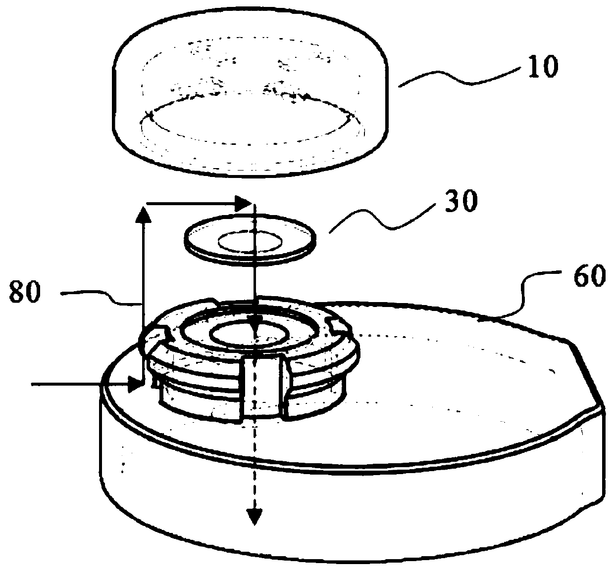
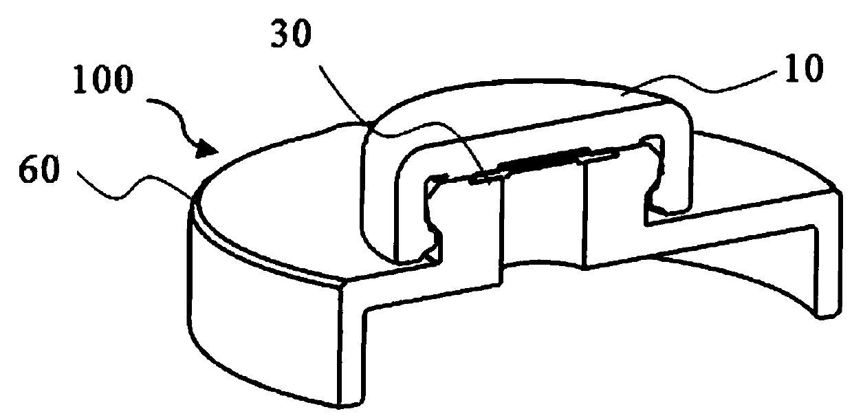
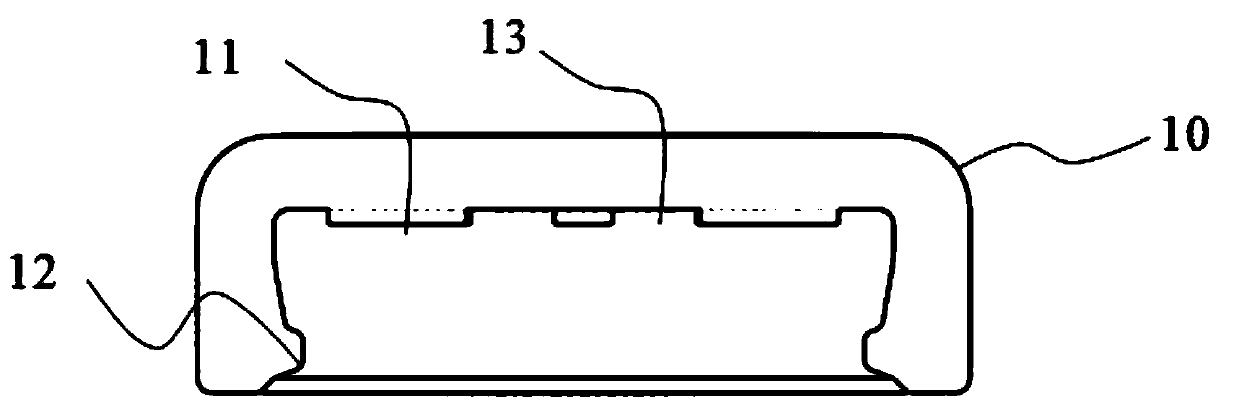
[0027] see Figure 1-6 , which discloses a protection structure for a gauge pressure sensor with an airflow direction change provided by an embodiment of the present invention, which is composed of a dustproof cap 10, a waterproof breathable membrane 30 and an upper cover 60;

[0028] Such as Figure 6 and figure 2 As shown, the protective structure 100 for changing the direction of air flow is installed on the gauge pressure sensor module 200 to form a protective cavity 30...


PUM


Abstract

The invention relates to the technical field of pressure sensors, and discloses an airflow turning protection structure for a gauge pressure sensor. The protection structure comprises a gauge pressuresensor module, and a protection part is arranged at the upper end of the gauge pressure sensor module. According to the invention, a turning airflow channel communicated with a protection cavity is formed between an upper cover and a dustproof cap and is matched with the protection cavity for use; a gas flow channel and a main gas flow channel on the side wall of the turning airflow channel enable gas to be turned to enter the protection cavity; when the pressure balance is achieved, impurities such as external large-particle dust and liquid cannot enter the airflow channel under the action of gravity; and even if part of light impurities can enter the airflow channel and are attached to the side wall of the airflow channel in the turning process, the airflow channel with the side walls arranged in the circumferential array mode can ensure good airflow passing performance, large-particle impurities are isolated while pressure balance is kept, and therefore the purpose of combined action of pressure balance and a protection structure is achieved.

Description

technical field [0001] The invention relates to the technical field of pressure sensors, in particular to a protective structure for changing the direction of airflow used in gauge pressure sensors. Background technique [0002] Pressure sensors are divided into two types: absolute pressure and gauge pressure. The absolute pressure sensor senses the difference between pressure and a fixed reference pressure; the gauge pressure sensor senses the difference between pressure and ambient pressure. Since the ambient pressure value is affected by temperature, humidity, altitude Influenced by other factors, the reference pressure values ​​in different environments are different. In order to ensure the output accuracy of gauge pressure sensors, it is necessary to ensure that the ambient pressure is balanced with the internal pressure of the sensor. [0003] In the prior art, while the internal pressure of the gauge pressure sensor is in balance with the ambient pressure, the harsh a...

Claims


Application Information

Patent Timeline
IPC IPC(8): G01L19/14G01L19/00
CPCG01L19/00G01L19/144
Inventor 王小平李凡亮吴登峰曹万
Owner WUHAN FINEMEMS
Why Eureka
Eureka Blog
Learn More