
Tunnel wind power generation device

A wind power generation device and tunnel technology, which is applied in the direction of wind power generation, wind power engine, wind power motor combination, etc., can solve the problem that the wind power generation device should not use the inner wall of the tunnel to collect wind energy, etc., and achieve long chemical toxicity pollution, good air flow direction, and enhanced vibration effect of effect

Active Publication Date: 2018-09-04
SOUTHWEST JIAOTONG UNIV
View PDF14 Cites 4 Cited by
  • Summary
  • Abstract
  • Description
  • Claims
  • Application Information

AI Technical Summary

Problems solved by technology

The subway tunnel wind power generation device described in the above two patents is not suitable for collecting wind energy on the inner wall of the tunnel

Method used


Image

  • Tunnel wind power generation device
  • Tunnel wind power generation device
  • Tunnel wind power generation device

Examples


Embodiment Construction

[0021] The present invention will be further described in detail below in conjunction with the accompanying drawings and specific embodiments.

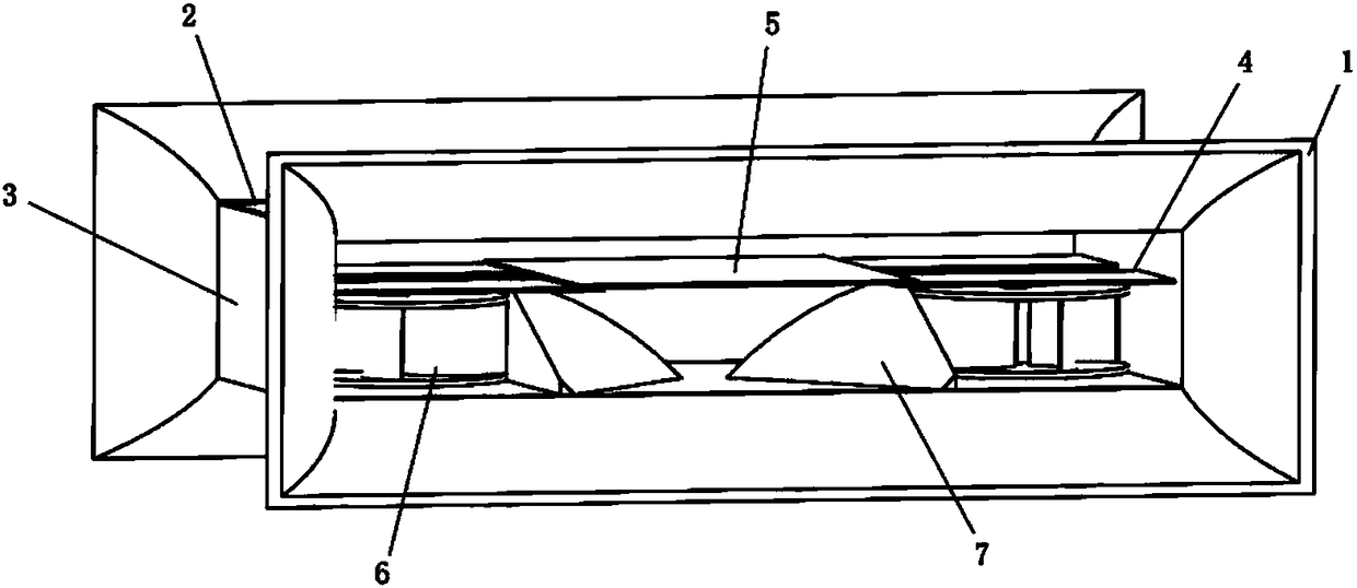
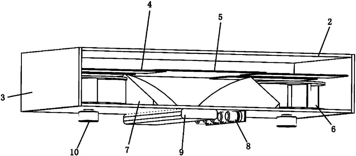
[0022] figure 2 , image 3 Shown is a tunnel wind power generation device, the cuboid frame is composed of left and right side plates 3 and upper and lower guard plates 2; the front air inlet and the rear air outlet of the frame are equipped with wind receiving covers 1; the left and right sides of the frame are A wind rotator 6 is provided on each side, and the shaft of the wind rotator 6 passes through the hole on the lower guard plate of the frame and is connected with the shaft of the generator 11. The edges of the left and right side plates of the frame are parallel to the upper and lower guard plates Piezoelectric sheets 4 are fixed in the direction of cantilever beams, and a vibrating plate 5 with a thickness of 0.3 mm is fixed on the inner ends of the two piezoelectric sheets at the same height, and is located under the fram...


PUM

PropertyMeasurementUnit
Thicknessaaaaaaaaaa

Abstract

The invention discloses a tunnel wind power generation device. With the adoption of the device, utilization of wind power in a tunnel and electric generation and energy supply functions can be realized. A framework is defined by a left side plate, a right side plate, an upper protecting plate and a lower protecting plate; two wind power receiving covers are fixed at front and back parts of the framework; electric generators on the outer sides of the protecting plates and wind power rotators on the inner sides of the protecting plate penetrate through the protecting plates to be connected; flowdeflectors are fixed between the two wind power rotators; two piezoelectric patches are arranged above each wind power rotator and embedded into the side plates on the two sides respectively; a vibrational thin plate is fixedly connected with the four piezoelectric patches; a storage battery and a rectifier are located in a casing outside the lower protecting plate; electric power generated by the electric generators and the piezoelectric patches is transmitted to the storage battery through the rectifier. The device adopts the tunnel wind power for power generation, has the characteristics of small size, high power generation and the like and is particularly suitable for being used in the railway tunnel.

Description

technical field [0001] The invention belongs to the technical field of design and manufacture of power generation mechanical devices, in particular a device that utilizes tunnel wind energy and piezoelectric vibration to generate power. Background technique [0002] With the increasing investment and operation scale of subway projects, more and more attention has been paid to the safety maintenance of subway tunnels. In this context, the tunnel health monitoring system based on wireless sensor network technology (WSN) has been well developed. The energy supply unit of wireless sensor nodes usually uses dry batteries, but due to the long running time and high frequency of the train, the time and personnel entering the tunnel are strictly limited, after the sensor is arranged, the battery is difficult to replace, and it cannot be powered by solar energy like the external structure. If it is exhausted, the nodes will lose their function, which greatly limits the development of...

Claims


Application Information

Patent Timeline
IPC IPC(8): F03D9/11F03D9/46F03D3/06F03D3/04H02N2/18
CPCH02N2/186F03D3/0427F03D3/062F03D9/11F03D9/46Y02E10/728Y02E10/74Y02B10/30Y02E70/30
Inventor 张祖涛漆令飞周启帆许攀朱袁罗静帆徐百川刘腾谦潘亚嘉刘昱岗
Owner SOUTHWEST JIAOTONG UNIV
Learn More