Energy storage battery module thermal runaway monitoring device, system and method

An energy storage battery and monitoring device technology, applied in the field of energy storage, can solve problems such as abnormal heating, battery thermal runaway, thermal runaway, etc., and achieve the effects of shortening the response time, improving the accuracy of early warning, and ensuring sensitivity

Inactive Publication Date: 2020-01-31
STATE GRID JIANGSU ELECTRIC POWER CO ELECTRIC POWER RES INST +3
View PDF5 Cites 6 Cited by
  • Summary
  • Abstract
  • Description
  • Claims
  • Application Information

AI Technical Summary

Problems solved by technology

[0003] The safety issue of energy storage technology has not yet been completely resolved. Represented by the most rapidly developing battery energy storage technology, abnormal heating and thermal runaway may occur during the centralized operation of large-scale energy storage batteries. , many fire accidents occurred in energy storage power stations, which caused significant economic losses and adverse social impacts; The probability of occurrence and the degree of danger have also been greatly increased. Therefore, real-time monitoring and early warning of the thermal runaway process of batteries are important measures to ensure the safe operation of energy storage power stations and promote the sustainable development of energy storage technology.
At present, the fire warning methods of energy storage batteries that are widely used are mostly smoke detection, temperature signal detection, infrared thermal imaging detection, combustible gas detection, etc. Alarm information can only be issued after smoke or flammable gas is detected, and there is still room for improvement in timely detection of battery fires

Method used


Image

  • Energy storage battery module thermal runaway monitoring device, system and method

Examples


Embodiment Construction

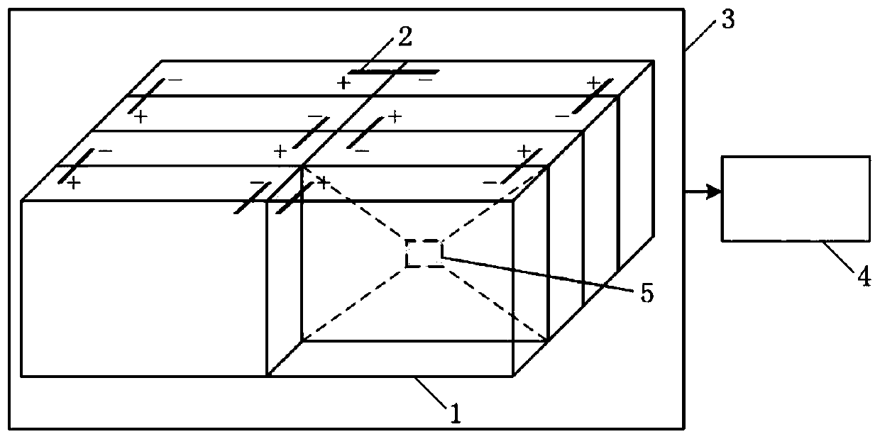
[0021] see figure 1 , the energy storage battery module thermal runaway monitoring device of the present invention includes a battery cell 1, a cell connection line 2 and a deformation pressure sensor 5, the cell connection line 2 connects the positive and negative electrodes of different battery cells 1 together, A battery module 3 is formed, and a deformation pressure sensor 5 is mounted on the surface of the battery cell 1 for transmitting monitoring signals to the battery management system 4 in real time.

[0022] Further, the battery cells 1 are energy storage batteries of solid structure or electric vehicle power batteries, and the connection mode between different battery cells 1 in the battery module 3 is series or parallel. The deformation pressure sensor 5 is installed at the center of the contact surface of the adjacent battery cells 1 .

[0023] An energy storage battery module thermal runaway monitoring system, comprising an energy storage battery module thermal ...


PUM


Abstract

The invention discloses an energy storage battery module thermal runaway monitoring device, system and method. The energy storage battery thermal runaway monitoring device comprises battery units, unit connecting wires and deformation pressure sensors; the positive poles and negative poles of different battery units are connected together through the unit connecting wires, so that a battery modulecan be formed; the deformation pressure sensors are arranged on the surfaces of the battery units respectively and are used for transmitting monitoring signals to a battery management system in realtime. The energy storage battery module thermal runaway monitoring system comprises an energy storage battery module thermal runaway monitoring device and a battery management system. According to theenergy storage battery module thermal runaway monitoring method, the deformation and stress of battery shells are monitored through the deformation pressure sensors. Compared with common smoke sensing, temperature monitoring and early warning and characteristic gas monitoring and early warning, the method can give an alarm in the early stage of thermal runaway of the batteries, greatly improve the sensitivity, reliability and real-time performance of the thermal runaway early warning of the energy storage batteries and improve the safe operation level of the energy storage batteries.

Description

technical field [0001] The invention relates to the field of energy storage technology, in particular to a thermal runaway monitoring device, system and method for an energy storage battery module. Background technique [0002] Energy storage refers to the process of storing energy through media or equipment and releasing it when needed. Energy storage technology is the key technology to solve the problems of large-scale access to renewable energy and abandoning wind and light. The necessary technology for the development of smart grid and energy Internet is also an important supporting technology to solve the peak-shaving and valley-filling of conventional power, and improve the efficiency, safety and economy of conventional energy generation and transmission. Energy storage technology can increase the ratio of clean energy power generation, realize the clean and efficient use of fossil energy, effectively reduce the emission of pollutants, and play a great role in the trea...

Claims


Application Information

Patent Timeline
Patent Type & Authority Applications(China)
IPC IPC(8): H01M10/42H01M10/48
CPCH01M10/425H01M10/482H01M10/488H01M2010/4271Y02E60/10
Inventor 孙磊刘洋陶风波朱洪斌蔚超马勇刘建军尹康涌郭东亮肖鹏
Owner STATE GRID JIANGSU ELECTRIC POWER CO ELECTRIC POWER RES INST
Why Eureka
Try Eureka