Mechanical supporting device for civil engineering surveying and mapping
A mechanical support and civil engineering technology, which is applied in the direction of mechanical equipment, machine platform/bracket, supporting machine, etc., can solve the problems of cumbersome operation, deflection of measuring instruments, deviation of measuring instruments from the edge of houses or foundation pits, etc.
- Summary
- Abstract
- Description
- Claims
- Application Information
AI Technical Summary
Problems solved by technology
Method used
Image
Examples
Embodiment 1
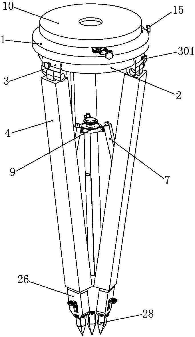
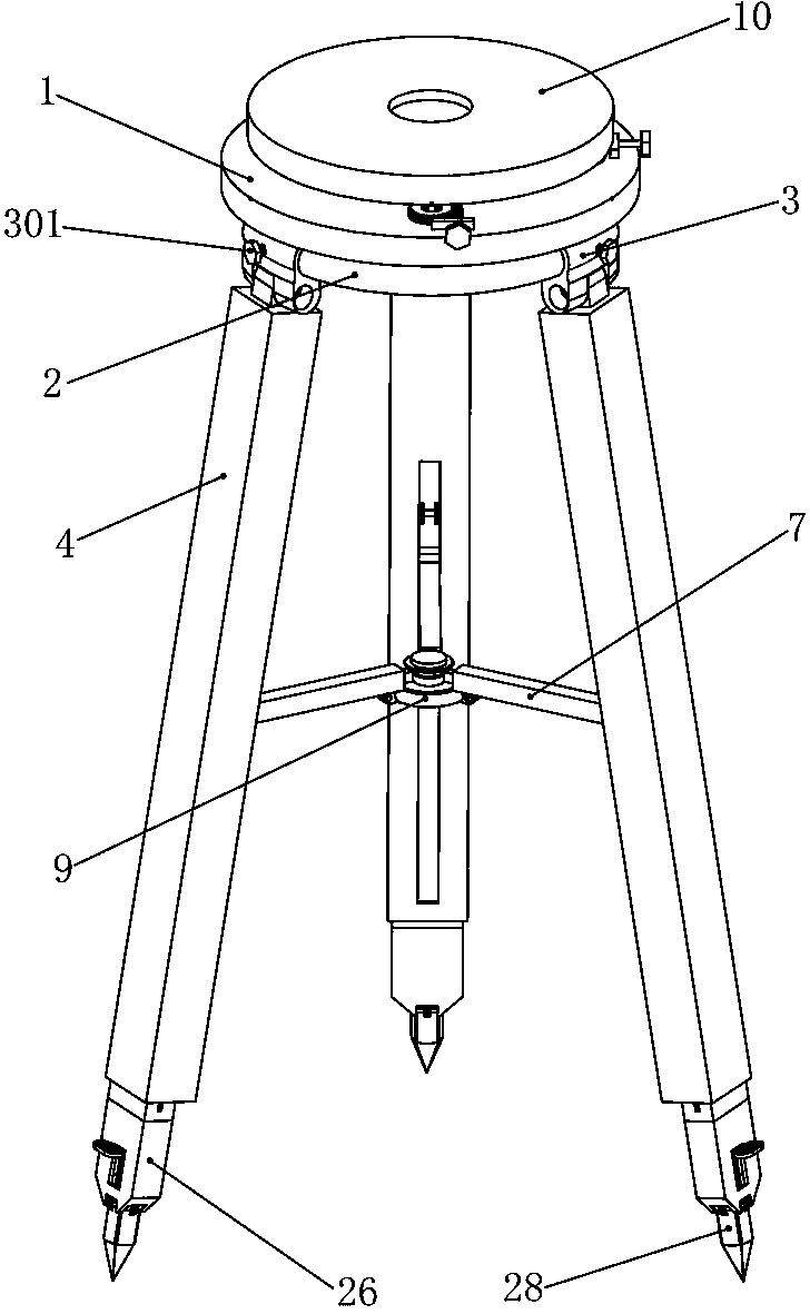
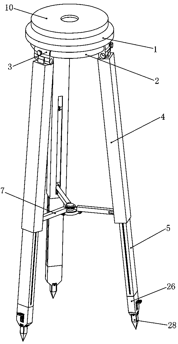
[0037]Embodiment 1, the present invention is a mechanical support device for civil engineering surveying and mapping, including a circular base 1, the base 1 is in the shape of a circular truncated cone, and it is characterized in that an annular leg is integrally connected to the outer edge of the base 1 Slide rail 2, the leg slide rail 2 is installed on the outer edge of the boss of the base 1, welding can be used here, or other common connection methods are adopted, and three leg slide rails are slidably installed on the leg slide rail 2 sleeve 3, each outrigger sliding sleeve 3 can slide on the outrigger sliding sleeve 2 respectively, and the outer sides of the three outrigger sliding sleeves 3 are respectively threaded with fixing bolts 301, when the outrigger sliding sleeve 3 slides to the corresponding After the position, tighten the fixing bolt 301 to fix the supporting leg sliding sleeve 3, and the lower ends of the three supporting leg sliding sleeves 3 are respective...
Embodiment 2
[0038] Embodiment 2, on the basis of Embodiment 1, the top ball of the base 1 is hinged with a mounting seat 10, the top surface of the mounting seat 10 is used to install measuring instruments, and the mounting seat 10 can be positioned in any direction on the base 1 Swing, the bottom surface of the mounting seat 10 is provided with two long chute 11, the two long chute 11 are respectively located on the front side and the right side of the axis of the mounting seat 10, and the top surface of the base 1 is provided with two A square bolt hole 12, the two bolt holes 12 are respectively located on the front side and the right side of the axis of the base 1, and respectively correspond to the position of a long chute 11, and the two bolt holes 12 are respectively slidably installed There are square fine-tuning bolts 13 with threads on four edges. The fine-tuning bolts 13 can only slide up and down in the bolt holes 12. The tops of the two fine-tuning bolts 13 are respectively bal...
Embodiment 3
[0039] Embodiment 3, on the basis of Embodiment 1, the front and rear inner walls of the three legs 4 are integrally connected with leg slide rails 401 respectively, and the front and rear sides of the three telescopic legs 5 are provided with slide rails respectively. The outrigger chute 501 on the outrigger slide rail 401, through the cooperation of the outrigger chute 501 and the outrigger slide rail 401, the telescopic outrigger 5 can only slide up and down in the outrigger 4 without shaking or deflection. shift.
PUM
 Abstract
Description
Claims
Application Information
 - R&D
- Intellectual Property
- Life Sciences
- Materials
- Tech Scout
- Unparalleled Data Quality
- Higher Quality Content
- 60% Fewer Hallucinations
Browse by: Latest US Patents, China's latest patents, Technical Efficacy Thesaurus, Application Domain, Technology Topic, Popular Technical Reports.
© 2025 PatSnap. All rights reserved.Legal|Privacy policy|Modern Slavery Act Transparency Statement|Sitemap|About US| Contact US: help@patsnap.com


