Check patentability & draft patents in minutes with Patsnap Eureka AI!

a fiber optic cable

A fiber optic cable, a pair of technology, applied to the fiber optic cable. It can solve the problems of short time of anti-ant effect, and achieve the effect of good anti-ant effect and long duration.

Active Publication Date: 2020-07-21
HANGZHOU FUTONG COMM TECH CO LTD
View PDF7 Cites 0 Cited by
  • Summary
  • Abstract
  • Description
  • Claims
  • Application Information

AI Technical Summary

Problems solved by technology

[0004] In view of the above problems, the present invention proposes an optical cable, which solves the defect that the existing optical cable uses physical anti-termites and its anti-termite effect time is short

Method used


Image

  • a fiber optic cable
  • a fiber optic cable

Examples


Embodiment 1

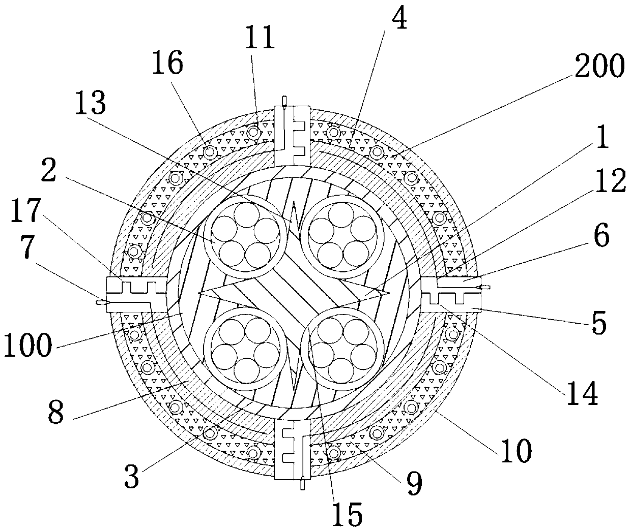
[0022] Such as figure 1 and figure 2 As shown, a kind of optical cable, comprises: optical cable core member 100 and detachable ant-proof assembly 200; Described optical cable core member comprises cross skeleton 1, is positioned at the optical fiber bundle 2 around cross skeleton and is positioned at the flame retardant layer 3 of outer skin; So Fiber paste is also filled between the cross frame and the flame-retardant layer.

[0023] The detachable anti-termite assembly includes four strip-shaped anti-ant units 4, and the two sides of the anti-ant units are respectively provided with a male plug 5 and a female plug 6 compatible with the male plug; the male plug is provided with At least one pair of connection heads 7; a waterproof hot-melt adhesive layer 8, a heat-resistant layer 9 and a nylon sleeve 10 are respectively provided between the male plug and the female plug from the inside to the outside. The male plug is provided with a pair of parallel strip-shaped sealing ...

Embodiment 2

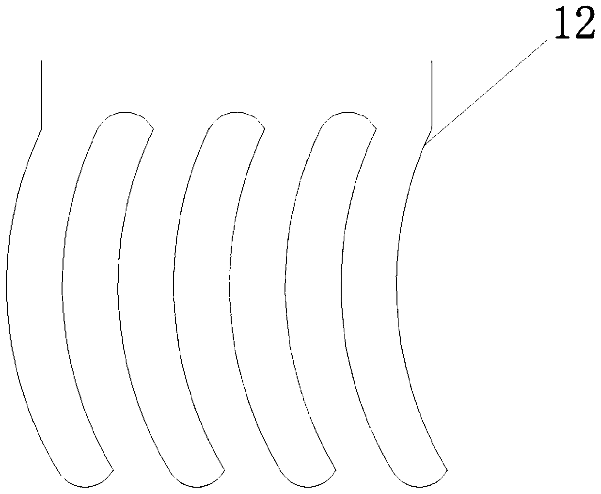
[0026] An optical cable, comprising: an optical cable core 100 and a detachable termite-proof assembly 200; the optical cable core includes a cross frame 1, an optical fiber bundle 2 positioned around the cross frame and a flame-retardant layer 3 positioned on an outer layer; the detachable The anti-ant component includes four strip-shaped anti-ant units 4, and the two sides of the anti-ant unit are respectively provided with a male plug 5 and a female plug 6 that is compatible with the male plug; the male plug is provided with at least one pair of terminals 7. The male plug and the female plug are respectively provided with a waterproof hot melt adhesive layer 8, a heat-resistant layer 9 and a nylon sleeve 10 from the inside to the outside; the anti-ant capsule 11 is fixed inside the heat-resistant layer, and the anti-ant An anti-ant solution is provided in the ant capsule; a heating wire 12 is provided in the waterproof hot melt adhesive layer, and two ends of the heating wir...


PUM

PropertyMeasurementUnit
melting pointaaaaaaaaaa

Abstract

The invention discloses an optical cable. The optical cable comprises an optical cable core part and a detachable anti-ant assembly; the optical cable core part comprises a cross skeleton, optical fibre bundles and a flame retardant layer; the optical fibre bundles are positioned at four sides of the cross skeleton; the flame retardant layer is positioned on the surface layer; the detachable anti-ant assembly comprises four long strip-shaped anti-ant units; a male plug and a female plug matched with the male plug are respectively arranged at two sides of the anti-ant unit; at least one pair ofconnection heads are arranged on the male plug; a waterproof hot melt glue layer, a heat resistant layer and a nylon sleeve are respectively arranged between the male plug and the female plug from inside to outside; an anti-ant capsule is fixed in the heat resistant layer; anti-ant solution is arranged in the anti-ant capsule; an electric heating wire is arranged in the waterproof hot melt glue layer; and two ends of the electric heating wire are connected onto a pair of connection heads of the male plug. According to the optical cable in the invention, physical ant prevention and chemical ant prevention are combined; the time of duration is long (for above ten years); the anti-ant effect is good; when breaking the nylon sleeve by biting, white ants can touch an anti-ant drug; and thus, the white ants can be effectively expelled.

Description

technical field [0001] The invention relates to the field of optical cable production, in particular to an optical cable. Background technique [0002] Optical cables are manufactured to meet optical, mechanical or environmental performance specifications. It is a communication cable assembly that uses one or more optical fibers placed in a sheath as a transmission medium and can be used individually or in groups. An optical cable is a communication line in which a certain number of optical fibers form a cable core in a certain way and is covered with a sheath to realize optical signal transmission; a cable formed by an optical fiber (optical transmission carrier) through a certain process. The basic structure of an optical cable is generally composed of several parts such as a cable core, a reinforced steel wire, a filler, and a sheath. In addition, there are components such as a waterproof layer, a buffer layer, and an insulated metal wire as required. [0003] Existing o...

Claims


Application Information

Patent Timeline
Patent Type & Authority Patents(China)
IPC IPC(8): G02B6/44H05B3/54
CPCG02B6/4401G02B6/443G02B6/4439H05B3/54
Inventor 乐成军周杭明刘法林
Owner HANGZHOU FUTONG COMM TECH CO LTD
Features
  • R&D
  • Intellectual Property
  • Life Sciences
  • Materials
  • Tech Scout
  • Unparalleled Data Quality
  • Higher Quality Content
  • 60% Fewer Hallucinations
Learn More