
Impeller for restraining cavitation of back surface of pump impeller blades and design method thereof

A technology of the back side of the blade and the pump impeller, which is applied to the blade design to suppress the cavitation on the back side of the pump impeller blade. Effect

Pending Publication Date: 2020-02-04
XIHUA UNIV
View PDF0 Cites 2 Cited by
  • Summary
  • Abstract
  • Description
  • Claims
  • Application Information

AI Technical Summary

Problems solved by technology

The purpose of the present invention is to solve the problem of cavitation caused by the low pressure on the back side of the impeller blade of the traditional r

Method used


Image

  • Impeller for restraining cavitation of back surface of pump impeller blades and design method thereof
  • Impeller for restraining cavitation of back surface of pump impeller blades and design method thereof
  • Impeller for restraining cavitation of back surface of pump impeller blades and design method thereof

Examples


Example Embodiment

[0044] Example one

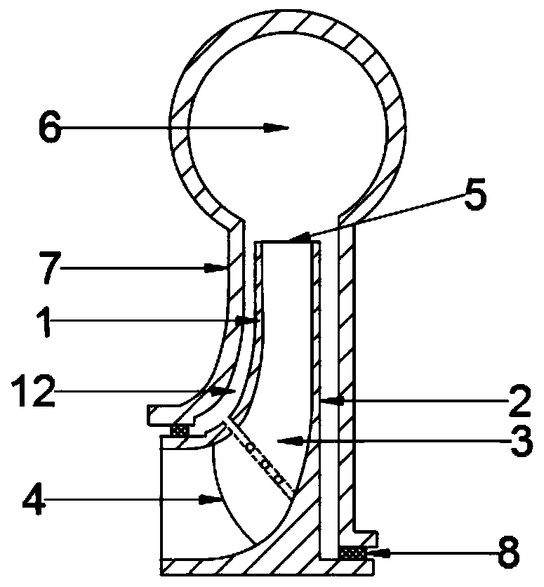
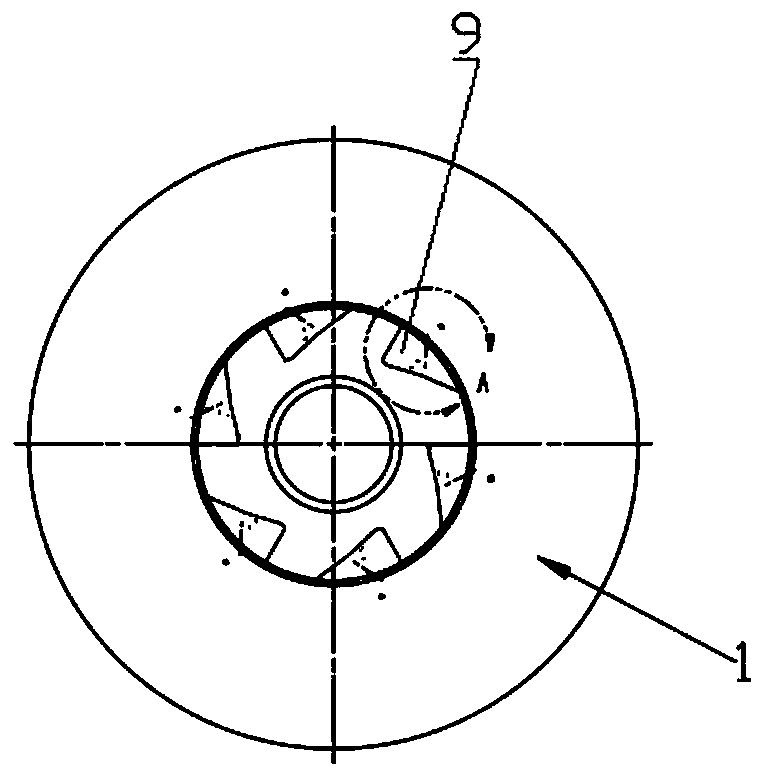
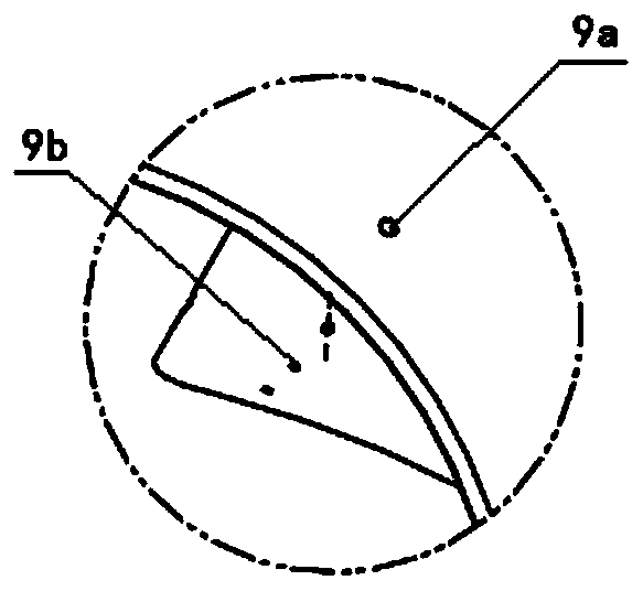
[0045] Such as Figure 1 to Figure 5 As shown, the pump of the present invention includes a pump impeller front cover 1, a pump impeller rear cover 2, a blade 3, a blade inlet 4, a blade outlet 5, a pressurized water chamber 6, a pump cover 7, a blade back 9, and a blade Working surface 10, sealing ring 8, rotating shaft 11. The water flow enters the pump from the water inlet edge 4 of the blade and flows through the blade area of ​​the pump. The blade working surface 10 of the pump works on the water flow to increase the kinetic energy of the water flow, and finally flows out from the water outlet edge 5 of the blade. When passing through the pressurized water chamber 6, the rotating motion of the liquid flowing out of the impeller is eliminated, the hydraulic loss caused by this is avoided, and the liquid flow speed is reduced, so that the kinetic energy is converted into pressure energy. As shown in the figure, the high pressure of the pressurized water c...

Example Embodiment

[0046] Example two

[0047] Such as Figure 6 to 1 As shown in 0, this embodiment and the first embodiment have the same features except for the following design; the hole punched from the position of the lowest pressure on the back of the blade 9 to the front cover 1 of the impeller is changed to a hole at the water outlet 5 leading to the lowest pressure on the back of the blade 9 Place.


PUM

PropertyMeasurementUnit
Hole diameteraaaaaaaaaa

Abstract

The invention discloses an impeller for restraining cavitation of the back surfaces of pump impeller blades and a design method of the impeller. The impeller is composed of an impeller front cover plate, an impeller rear cover plate and a plurality of sets of blades symmetrically arranged between the impeller front cover plate and the impeller rear cover plate. Each set of blades comprises a bladeworking face, a blade back face opposite to the blade working face, a blade water inlet edge and a blade water outlet edge, a plurality of holes are formed in the lowest pressure point area of the blade back face, and all the holes are communicated with holes formed in the impeller front cover plate or holes formed in the blade water outlet edge through the same pipeline arranged in the blades. According to the pump impeller, the pressure of the back face of the blade cannot reach the environment vaporization pressure, cavitation of the back face of the blade can be restrained, the problem that the pressure from the front face of the blade to the back face of the blade is insufficient can be solved, the pressure selectable range is enlarged, and the blade back face cavitation phenomenon is restrained.

Description

technical field [0001] The invention belongs to the technical field of mechanical design, in particular to the technical field of hydraulic rotating machinery design, in particular to a blade design method for suppressing cavitation at the back of a pump impeller blade and the designed impeller. Background technique [0002] Cavitation is a liquid phenomenon. When the temperature of the liquid is constant and the pressure is reduced to a certain critical pressure, the liquid will vaporize or the air dissolved in the liquid will develop to form a cavity. This phenomenon is called cavitation. It has obvious three-dimensional flow characteristics and violent unsteady characteristics, and widely exists in hydraulic machinery and hydraulic engineering. When the cavitation enters the area with large pressure changes with the liquid flow, it loses the conditions of existence and suddenly collapses, causing the liquid movement around the original cavitation to increase the pressure ...

Claims


Application Information

Patent Timeline
IPC IPC(8): G06F30/23G06F30/17G06T17/00
CPCG06T17/00
Inventor 张惟斌张慧宇詹月灵韩宇明江启峰衡亚光刘小兵何坤健成昱其
Owner XIHUA UNIV
Learn More