Centrifugal pump volute for cavitation suppression and design method and installation method thereof

A design method and technology for centrifugal pumps, applied in the field of centrifugal pumps, can solve problems such as abnormal vibration of impeller and pump body, metal erosion, noise generation, etc., and achieve the effect of delaying cavitation, increasing fluid pressure, and inhibiting cavitation.

Pending Publication Date: 2022-02-08
ZHEJIANG HANYI ELECTROMECHANICAL CO LTD
View PDF0 Cites 1 Cited by
  • Summary
  • Abstract
  • Description
  • Claims
  • Application Information

AI Technical Summary

Problems solved by technology

[0002] Centrifugal pump cavitation will cause abnormal vibration of impeller and pump body, generate noise, and cause unstable operation, and reduce hydraulic performance such as head and efficiency
Running in a cavitation state for a long time will also cause denudation of the metal on the impeller surface of the centrifugal pump, shortening the life of the pump body

Method used


Image

  • Centrifugal pump volute for cavitation suppression and design method and installation method thereof
  • Centrifugal pump volute for cavitation suppression and design method and installation method thereof
  • Centrifugal pump volute for cavitation suppression and design method and installation method thereof

Examples


Embodiment Construction

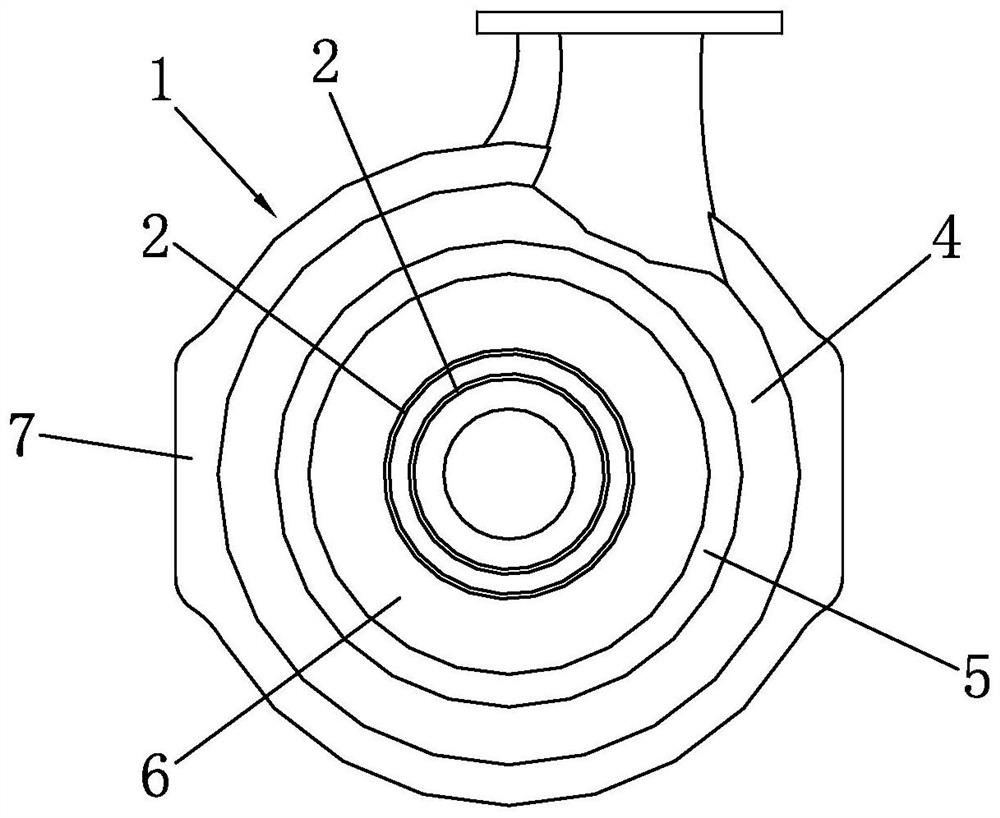
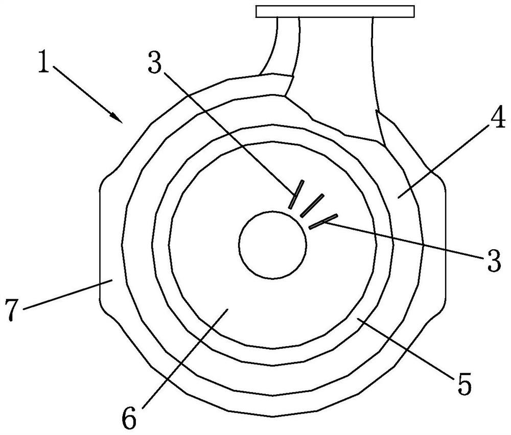
[0075] Such as figure 1 with figure 2 Shown are the first and second embodiments of the centrifugal pump volute used for cavitation suppression in the present invention, the first embodiment is designed for the circumferential groove 2, and the second embodiment is designed for the radial groove 3.

[0076] The centrifugal pump volute used for cavitation suppression includes a volute body 1 , and a volute chamber is arranged inside the volute body 1 , and an impeller is installed in the volute chamber. The volute body 1 is provided with a groove, the groove has a certain depth and width, and the groove adopts the circumferential groove 2 and the radial groove 3, and the circumferential groove 2 or the radial groove 3 is arranged on the inner side of the volute body 1 , through the accumulation of fluid in the groove, the pressure at the location of the leakage vortex is increased, the low pressure area generated by the leakage vortex is reduced, and the generation of cavitat...


PUM


Abstract

The invention discloses a centrifugal pump volute for cavitation suppression and a design method and an installation method thereof, wherein the centrifugal pump volute comprises a volute body, the volute body is provided with grooves, the grooves are annular grooves and radial grooves, and the annular grooves or the radial grooves are formed in the inner side of the volute body; and fluid is accumulated in the grooves, the pressure of the position where leakage vortexes are located is improved, a low-pressure area generated by the leakage vortexes is reduced, and cavitation is restrained on the premise that hydraulic characteristics such as lift efficiency are not reduced basically. According to the design method, the grooves are designed, and the positions, the shapes and the sizes of the grooves are determined. According to the installation method, a shell, a first side plate and a second side plate are mounted according to the design result, the manufacturing quality of the shell, the first side plate and the second side plate can be conveniently controlled, the annular grooves or the radial grooves can be conveniently formed in the second side plate, the positions and the shapes of the grooves can be conveniently controlled, and meanwhile it is ensured that the width and the depth of the grooves meet the design requirement.

Description

technical field [0001] The invention belongs to the technical field of centrifugal pumps, in particular to a centrifugal pump volute used for cavitation suppression, its design method and its installation method. Background technique [0002] Centrifugal pump cavitation will cause abnormal vibration of the impeller and pump body, generate noise, and cause unstable operation, reducing hydraulic performance such as head and efficiency. Long-term operation in the cavitation state will also cause denudation of the metal on the impeller surface of the centrifugal pump, shortening the life of the pump body. Therefore, the centrifugal pump should avoid cavitation during actual operation. [0003] For open and semi-open centrifugal pumps, due to the relative motion between the impeller and the volute, the pressure difference between the suction surface and the pressure surface causes leakage flow at the top of the impeller, and a leakage vortex is formed at the tip of the impeller ...

Claims


Application Information

Patent Timeline
Patent Type & Authority Applications(China)
IPC IPC(8): F04D29/42F04D29/66B23P15/00G06F30/28G06F30/23
CPCF04D29/426F04D29/669B23P15/00G06F30/28G06F30/23G06F2113/08G06F2119/14
Inventor 潘华杰
Owner ZHEJIANG HANYI ELECTROMECHANICAL CO LTD
Why Eureka
Try Eureka