Shock absorber

a technology of shock absorber and shock absorber, which is applied in the direction of shock absorber, liquid based damper, vibration damper, etc., can solve the problems of unstable damping force, and achieve the effect of reducing the occurrence of aeration and cavitation and superior productivity

Active Publication Date: 2018-07-03
HITACHI ASTEMO LTD
View PDF7 Cites 1 Cited by
  • Summary
  • Abstract
  • Description
  • Claims
  • Application Information

AI Technical Summary

Benefits of technology

[0005]An object of the present invention is to provide a shock absorber capable or suppressing the occurrence of aeration and cavitation without providing a baffle plate in the reservoir and hence exhibiting superior productivity.
[0006]To solve the above-described problem, the present invention provides a shock absorber including a cylinder having a hydraulic fluid sealed therein, a piston disposed or inserted in the cylinder, a piston rod connected to one piston and extended to the outside of the cylinder, an outer tube provided around the outer periphery of the cylinder, a reservoir formed between the cylinder and the outer tube and having the hydraulic fluid and a gas sealed therein, a separator tube provided between the cylinder and the outer tube to form a passage between the separator tube and the cylinder, which passage communicates with the interior of the cylinder, a separator tube opening formed in a side wall of the separator tube, an opening provided in a side wall of the outer tube to face the separator tube opening, a casing secured to the side wall of the outer tube such that the interior of the casing communicates with the reservoir through the opening, a damping force generating mechanism housed in the casing and connected to the separator tube opening to generate a damping force by controlling a flow of the hydraulic fluid, and a regulating part provided in the casing to restrict the occurrence of a circumferential flow of hydraulic fluid at a point of intersection between the direction of a flow of hydraulic fluid flowing from the interior of the casing toward the reservoir and the axial direction of the reservoir.

Problems solved by technology

In a shock absorber having a reservoir as stated above, if the gas in the reservoir gets mixed into the hydraulic oil as bubbles or dissolves in the hydraulic oil, aeration or cavitation may occur, causing the damping force to become unstable.

Method used


Image

  • Shock absorber
  • Shock absorber
  • Shock absorber

Examples


first embodiment

[0018]the present invention will be explained blow with reference to FIGS. 1 to 3.

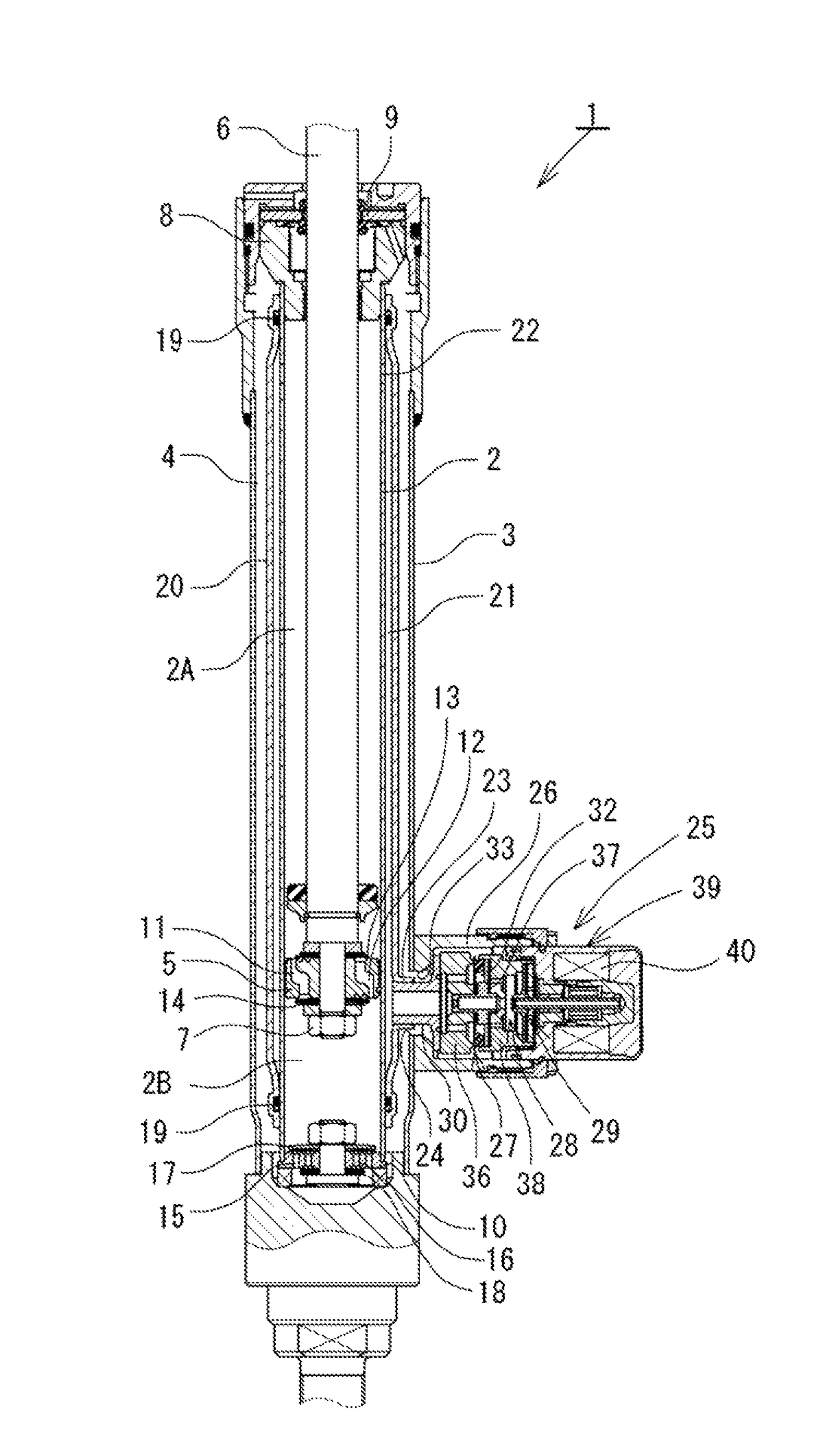
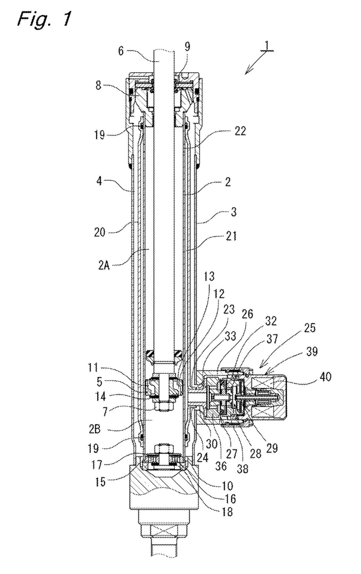
[0019]As shown in FIG. 1, a shock absorber 1 according to this embodiment is a tube-type damping force control hydraulic shock absorber. The shock absorber 1 has a double-tube structure comprising a cylinder 2 and an outer tube 3 provided around the outer periphery of the cylinder 2. Between the cylinder 2 and the outer tube 3, an annular reservoir 4 is formed. The cylinder 2 has a piston 5 slidably fitted therein. The piston 5 divides the interior of the cylinder 2 into two chambers, i.e. a cylinder upper chamber 2A and a cylinder lower chamber 2B. The piston 5 has one end of a piston rod 6 connected thereto by a nut 7. The other end of the piston rod 6 extends through the cylinder upper chamber 2A and through a rod guide 8 and an oil seal 9, which are provided in the upper end of the double-tube structure comprising the cylinder 2 and the outer tube 3. The other end of the piston rod 6 extends to the...

second embodiment

[0040]A shock absorber according to the present invention will be explained below with reference to FIGS. 6 and 7.

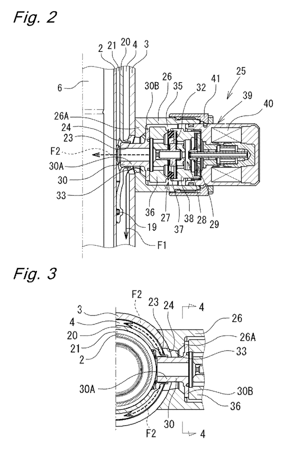
[0041]As shown in FIGS. 6 and 7, the shook absorber according to the second embodiment has a passage groove 34A formed on the bottom 26A of the casing 26 in addition to the passage groove 34. The passage groove 34A has a substantially inverted V-shape in front view (see FIGS. 6 and 7) and extends from near the inner peripheral surface at the lower side of the casing 26 to the opening 33. The passage groove 34A is formed in such an inverted V-shape that the passage groove 34A is forked at a lower end thereof and tapers toward an upper end thereof at which the passage groove 34A communicates with the opening 33. Consequently, the bottom 26A of the casing 26 has a substantially X-shaped groove formed from the passage groove 34 and the passage groove 34A in combination.

[0042]With the above-described structure, the hydraulic oil flowing from the chamber 35 in the casing 26 to...

third embodiment

[0043]Next, a shock absorber according to the present invention will be explained with reference to FIGS. 8 to 10.

[0044]In the shook absorber according to the third embodiment, as shown in FIGS. 8 to 10, the bottom of the casing 26 is provided in the form of a bottom plate 26B which is a discrete member separate from the casing 26. The bottom plate 26B is formed with a substantially V-shaped passage groove 34. The bottom plats 26B is abutted against an inward flange portion 26C formed at the outer tube 3 side end of the casing 26 and secured, together with the passage member 30, by thread-connecting the solenoid assembly 39 to the opening of the casing 26.

[0045]With the above-described structure, the third embodiment offers operational advantages similar to those of the foregoing first embodiment.


PUM


Abstract

A flow of hydraulic oil induced by sliding movement of a piston in a cylinder is controlled by a damping force generating mechanism to generate a damping force. A flow of hydraulic oil from a casing of the damping force generating mechanism toward a reservoir is regulated by a passage groove formed on the bottom of the casing so as to be directed downward in the reservoir. Thus, the hydraulic oil is efficiently supplied to a base valve from the damping force generating mechanism even when the hydraulic oil is sucked from the reservoir into a cylinder lower chamber through a passage in the base valve during the extension stroke of a piston rod. Therefore, it is possible to suppress a sharp reduction in pressure in the lower part of the reservoir and hence possible to suppress the occurrence of aeration and to obtain stable damping force characteristics.

Description

BACKGROUND OF THE INVENTION[0001]The present invention relates to shock absorbers that generate a damping force by controlling a flow of hydraulic fluid in response to a stroke of a piston rod.[0002]Tube-type shock absorbers attached to suspension systems of vehicles, for example, automobiles, are generally arranged as follows. A piston with a piston rod connected thereto is inserted in a cylinder having a hydraulic oil sealed therein as a hydraulic fluid. A stroke of the piston rod causes sliding movement of the piston in the cylinder, which in turn induces a flow of hydraulic oil. The hydraulic oil flow is coat roiled by a damping force generating mechanism, which comprises an orifice, a disk valve, etc., to generate a damping force. Shock absorbers of this type include one in which a reservoir having a hydraulic oil and a gas sealed therein is connected to the cylinder to compensate for a cubic capacity change in the cylinder caused by the entry and exiting of the piston rod into...

Claims


Application Information

Patent Timeline
Patent Type & Authority Patents(United States)
IPC IPC(8): F16F9/34F16F9/32F16F9/18F16F9/46
CPCF16F9/34F16F9/46F16F9/3257F16F9/185F16F9/19F16F9/32F16F9/48
Inventor KIMURA, YUSEIKATAYAMA, YOHEIHARADA, NAOFUMISHIMAZAKI, SATOSHI
Owner HITACHI ASTEMO LTD
Why Eureka
Try Eureka