Cavitation suppressionwing section device

An airfoil and cavitation technology, applied in the direction of mechanical equipment, fluid flow, etc., can solve problems such as flow instability on the suction surface, achieve the effects of suppressing cavitation, reducing production cycle, and increasing pressure

Active Publication Date: 2020-10-30
JIANGSU UNIV
View PDF7 Cites 1 Cited by
  • Summary
  • Abstract
  • Description
  • Claims
  • Application Information

AI Technical Summary

Problems solved by technology

However, on the other hand, although the existing products can supplement the pressure on the suction surface, the direct pressure difference between the suction surface and the pressure surface is relatively large, which will lead to a state of flow instability on the suction surface. The airfoil structure that suppresses the above-mentioned deficiencies and cavitation is imminent

Method used


Image

  • Cavitation suppressionwing section device
  • Cavitation suppressionwing section device
  • Cavitation suppressionwing section device

Examples


Embodiment Construction

[0032] The present invention will be further described below in conjunction with the accompanying drawings and specific embodiments, but the protection scope of the present invention is not limited thereto.

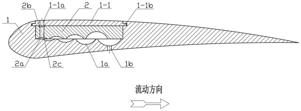
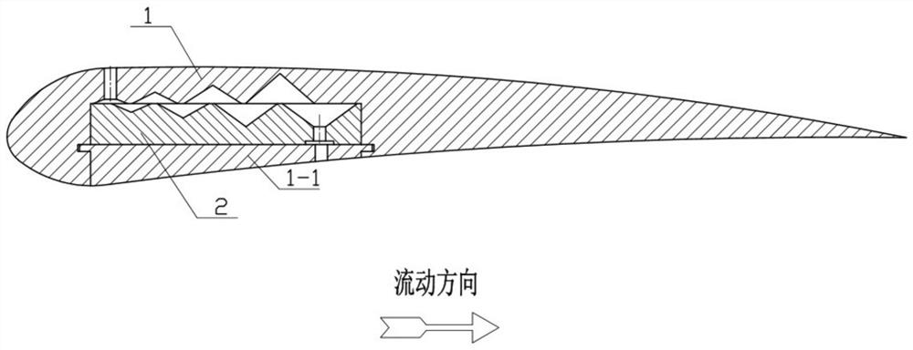
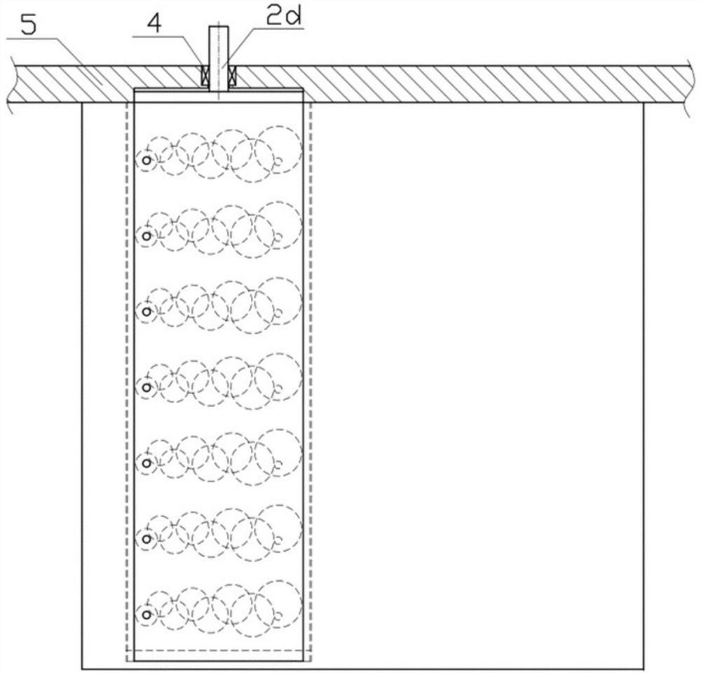
[0033] Such as figure 1 with Figure 4 As shown, the cavitation suppression airfoil device of the present invention includes an airfoil 1 and a slider 2, the slider 2 is movably installed in the airfoil 1, and any sliding surface of the slider 2 is provided with Several second grooves 2a arranged in a rectangle, the surface of the airfoil 1 in contact with any sliding surface is provided with a number of rectangular first grooves 1a, through the movement of the slider 2, any slider 2 The second groove 2a on the sliding surface communicates with at least the adjacent first groove 1a on the surface of the airfoil 1 that is in contact with it, so as to form at least one pressure-reducing channel along the flow direction; The airfoil 1 is provided with an inlet and outlet c...


PUM


Abstract

The invention provides a cavitation suppression wing section device which comprises a wing section and a sliding block. The sliding block is movably mounted in the wing section. Multiple arranged grooves are arranged on any sliding face of the sliding block and the surface, in contact with the sliding face, of the wing section. Through moving of the sliding block, the grooves on any sliding face of the sliding block at least communicate with the adjacent grooves on the surface, in contact with the sliding face, of the wing section, and the grooves are used for forming at least one pressure reduction runner in the flowing direction. An inlet and outlet communicating with the pressure reduction runners is arranged on the wing section. Through moving of the sliding block, the passage cross sections between the grooves on the sliding block and the grooves on the wing section are changed to be used for adjusting the flowing capacity of the pressure reduction runners. According to the cavitation suppression wing section device, the structure is simple and compact, the adjustable pressure reduction runners can meet the specific anti-cavitation requirements of fluid machines running underdifferent work conditions, and the device has wide development space and application prospects.

Description

technical field [0001] The invention relates to the field of fluid machinery, in particular to a cavitation suppressing airfoil device. Background technique [0002] During the operation of fluid machinery, when the temperature is constant and the pressure inside the flow field drops to the saturated vapor pressure, the fluid medium will vaporize, and the gas dissolved in the liquid will precipitate out and gradually develop into cavitation. When the cavitation flows into the high-pressure area along with the fluid medium, the cavitation is squeezed and will shrink or even collapse. Accompanied by the generation, development and collapse of voids, a series of physical changes will also occur, and this process is called cavitation. Cavitation is a seriously harmful phenomenon in hydraulic machinery, which will cause serious vibration, noise and cavitation problems. Taking effective measures to control its occurrence is of great significance to the safe operation of hydraulic...

Claims


Application Information

Patent Timeline
Patent Type & Authority Applications(China)
IPC IPC(8): F15D1/00
CPCF15D1/00
Inventor 龙云安策朱荣生陈一鸣付强王秀礼
Owner JIANGSU UNIV
Why Eureka
Try Eureka