Reversible pump-turbine installation

a pump-turbine and rotor technology, applied in water-power plants, machines/engines, liquid fuel engines, etc., can solve the problems of less than 100 mw, inconvenient excavation and underground construction, and required a deep and expensive excavation, so as to maximize the ratio of impeller tip diameter, maximize the head per stage, and increase the effect of head

Active Publication Date: 2022-04-12
BHE TURBOMACHINERY LLC
View PDF56 Cites 1 Cited by
  • Summary
  • Abstract
  • Description
  • Claims
  • Application Information

AI Technical Summary

Benefits of technology

[0006]The proposed configuration utilizes a simple and inexpensive borehole of perhaps 1 to 3 meters in diameter to position a high specific output reversible pump-turbine sufficiently below tailwater elevation to suppress cavitation. Such boreholes are routinely drilled as a commodity construction service for reasonable prices. A steel liner and conduits for hoisting water, electrical and control cables, for example, may be grouted in place within the borehole. Pump-turbines adapted to this type of installation may be configured as single stage machines or may be configured as multi-stage machines utilizing specially configured “diffuser bowls” similar in function to those used on multi-stage submersible pumps. These pump-turbines would not normally use conventional scroll cases. As such, stages of these pump-turbines may be stackable to allow standard hydraulic designs to be used over a wide range of head conditions. The use of standard pump-turbine stages is further facilitated by the fact that the required plant cavitation coefficient can be achieved by simply establishing the required vertical borehole depth. Compared to conventional underground powerhouse pump-turbine installations, there is a less frequent need to design and manufacture site specific machinery and there is no need carry the penstock nor tailrace conduit to extraordinary depths, which would be cost prohibitive in conjunction with small pumped hydro installations at most locations. The use of standard components results in increased quantities of like parts at reduced cost. Reduced costs in turn enable a greater number of projects to be built with increased part quantities.
[0007]Water flow to and from the reversible pump-turbine may be through coaxial penstocks positioned in the borehole above the pump-turbine assembly. The associated motor-generator, which can act as a motor or generator as conditions demand, may be submersible and in certain preferred embodiments located below the pump-turbine(s). Locating the motor-generator below the pump turbines allows for a larger diameter, and therefore more economical, motor-generator for a given borehole size. Allocating substantially all of the borehole cross sectional area to water conveyance (up and down), rather than to space for the motor-generator, allows for the maximum power rating for a given diameter of borehole.
[0008]The motor-generator may alternatively be located outside of the water passageways and connected to the runner with a shaft. Such an arrangement may be cheaper than providing an underground powerhouse large enough to incorporate a scroll case, while allowing the use of a readily available air-cooled motor-generator.
[0009]In a preferred embodiment, a removable manifold may be used to connect the inner pipe to tailwater and connect the outer pipe to the penstock leading to headwater. It is generally more efficient to connect the smaller diameter pump inlet / turbine outlet with the smaller of the coaxial pipes while connecting the larger pump outlet / turbine inlet with the larger of the two coaxial pipes. Alternative embodiments of this invention may utilize another arrangement as may be the case when multiple pump turbines might be installed, on a bulkhead, for example, in a common borehole. The removable manifold may include an integral pneumatically controlled pressure relief valve. This integral pressure relief valve will itself reduce civil works costs by eliminating the need for a surge shaft and by reducing penstock surge pressure and penstock cost. Additionally, or alternatively, an air cushion may be left under the cover of the borehole. Removal of the manifold allows removal of the machinery from the borehole. Dedicated hoisting equipment will facilitate installation, service, and maintenance without the need for confined space work. A water pressure actuated piston attached to the bottom of the reversible pump turbine may be used for raising and lowering. A spacer between the piston and the machine may be used to allow the machine to be raised entirely clear of the borehole.
[0016]In accordance with a further aspect of the invention a reversible pump turbine runner or pump impeller is provided that imparts to the flow an upward velocity component. This upward velocity component allows the flow to proceed directly up through the diffuser or a guide vane-diffuser combination in the case of a reversible pump-turbine, or directly to a diffuser (stator) stage in the case of a multi-stage pump, while maximizing the ratio of impeller tip diameter to maximum water passageway diameter. In the case of the present invention this ratio may be 1.00. This maximizes the head per stage and allows a greater head to be achieved with a single stage machine. FIGS. 19a, 19b, and 19c illustrate the flow in the meridional plane as well as the X-shaped appearance of the impeller blades when viewed toward the trailing edge.

Problems solved by technology

Positioning of the runner below tailwater has heretofore required a deep and expensive excavation regardless of machine size and rating.
The expense of excavation and underground construction has been cost prohibitive for small installations, of less than 100 MW, for example.
Sites suitable for large installations are limited by geology, geography, competing land uses, and adequate transmission lines.
Many suitable smaller scale sites exist, but existing reversible pump-turbines, even if scaled down in size and rating, still require excavation and construction costs that are prohibitive.

Method used


Image

  • Reversible pump-turbine installation
  • Reversible pump-turbine installation
  • Reversible pump-turbine installation

Examples


Embodiment Construction

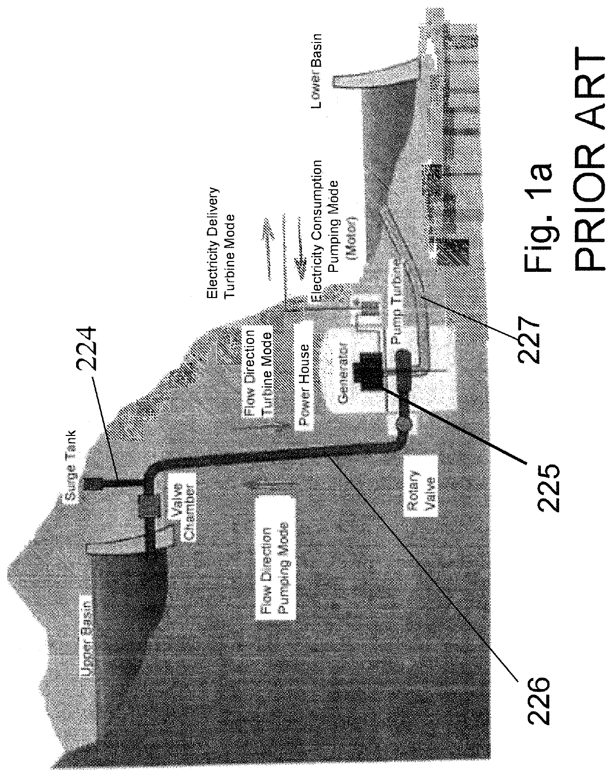
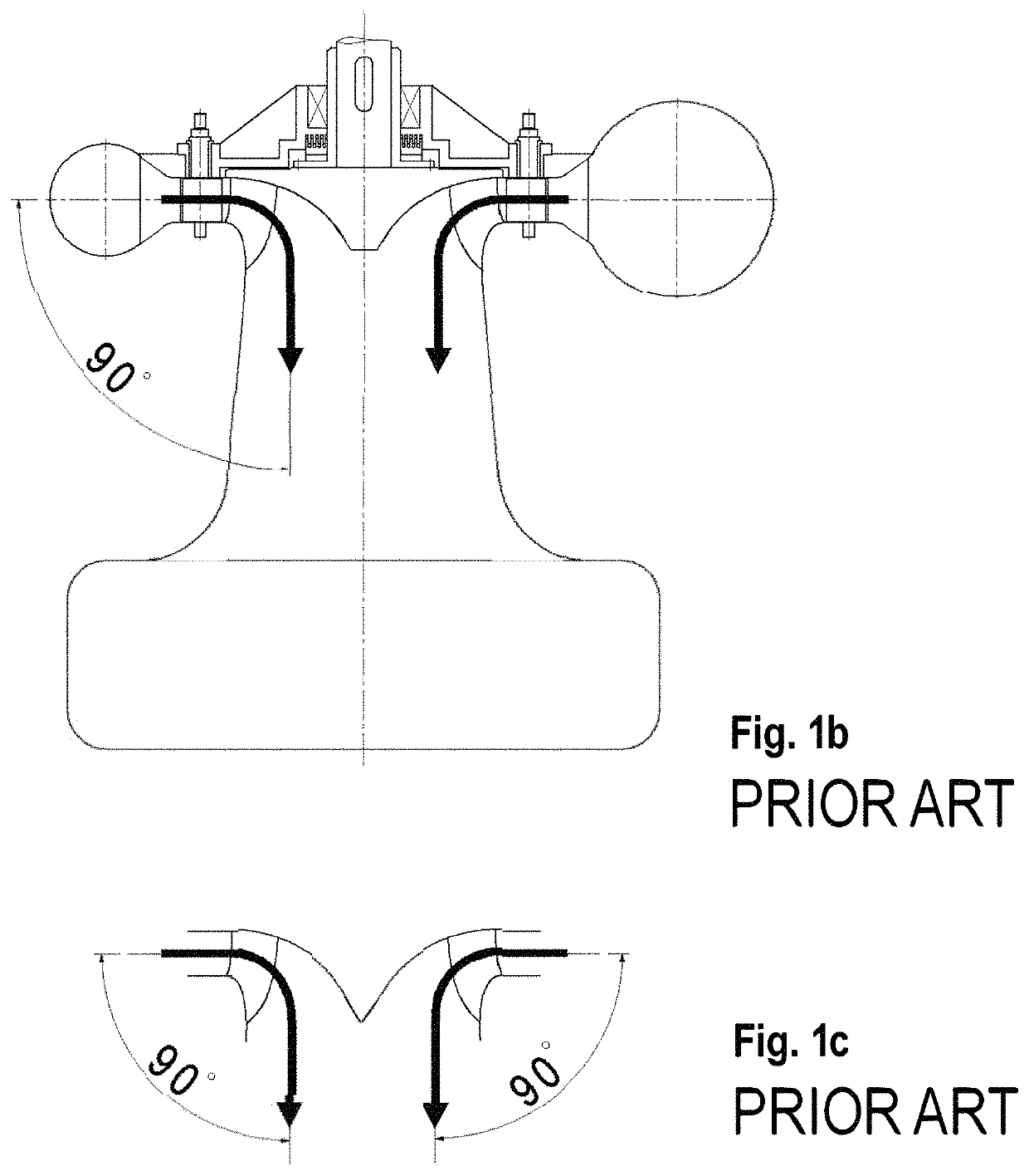
[0054]Referring to FIGS. 1a, 1b, and 1c, a conventional pumped storage plant with a reversible pump-turbine is shown. There are several notably expensive features in such a conventional installation. These include;[0055]1) A surge shaft 224 is typically needed to relieve waterhammer that can result from a load rejection.[0056]2) An underground powerhouse 225 below tailwater level. Such a powerhouse is expensive to construct and is at risk of flooding due to human error or component failure. Flooding of an underground powerhouse is a hazard to the facility itself as well as to its operators.[0057]3) The penstock 226 and tailrace conduit 227 must be routed, at great expense to the same low elevation as the powerhouse itself.

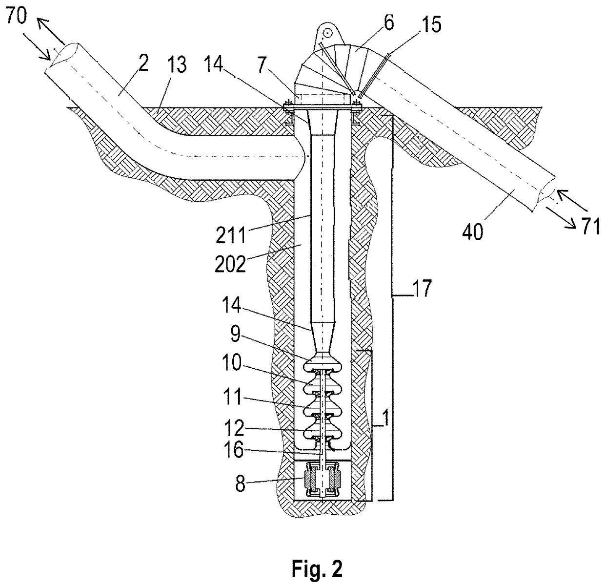
[0058]Referring to FIGS. 2 and 3, a reversible pump-turbine installation in accordance with the present invention is shown. No underground powerhouse is required. Instead, a vertical borehole 17 allows the pump-turbine and motor-generator assembly 1 to be installed...


PUM


Abstract

The present invention is a reversible pump-turbine installation positioned in a vertical borehole instead of in a conventional underground powerhouse or deep concrete powerhouse. The required plant cavitation coefficient may be achieved by simply boring a vertical borehole to the required depth rather than routing the water flow to and from a deeply buried powerhouse. A pneumatically controlled pressure relief valve may be incorporated into this invention.

Description

[0001]This application is the United States National Stage of International Application No. PCT / US2018 / 030310, filed Apr. 30, 2018, which is a Continuation in Part of International Application No. PCT / US2017 / 048769, filed Aug. 26, 2017, and which also claims benefit of and priority to U.S. Provisional Application No. 62 / 664,849 filed Apr. 20, 2018 and U.S. Provisional Application No. 62 / 527,010, filed Jun. 29, 2017. Each said application is incorporated herein by reference.[0002]This invention was made with government support under DE-EE0008014 awarded by the Department of Energy. The government has certain rights in the invention.FIELD OF THE INVENTION[0003]The present invention relates to reversible pump-turbines used for storage of electrical energy. Conventional pumped storage facilities as shown in FIG. 1 generally use an underground powerhouse to provide sufficient absolute pressure at the runner to prevent destructive cavitation. The elevation of the runner may be 100 meters ...

Claims


Application Information

Patent Timeline
Patent Type & Authority Patents(United States)
IPC IPC(8): F03B13/06E02B9/00F03B3/10E02B9/06F03B13/10
CPCF03B13/06E02B9/00E02B9/06F03B3/103F03B13/10F05B2220/32F03B13/02Y02E10/20Y02E60/16F03B3/18F04D29/506F04D1/04F04D29/2238F04D29/2283F04D29/4293F04D29/448F04D29/548
Inventor OBERMEYER, HENRY K.IAVORNIC, CLAUDIU M.BAKER, GRANT QUINN
Owner BHE TURBOMACHINERY LLC
Why Eureka
Try Eureka