Image processing method and device, electronic equipment and readable storage medium
An image processing and image technology, which is applied in the field of endoscopy to achieve the effect of intuitive and clear images and easy observation.
Active Publication Date: 2020-02-04
SONOSCAPE MEDICAL CORP
6 Cites 6 Cited by
AI-Extracted Technical Summary
Problems solved by technology
But its color border due to imagi...
Method used
Based on above-mentioned technical scheme, the present embodiment is by extracting the boundary area image of the color endoscopic image in time-series sampling video, and determine boundary point, according to the pixel point information and boundary point in the preset area scope of boundary point determine In order to replace the boundary point value in the original color endoscope image with the repair value, the image can be repaired, which can solve the image repair problem of the color boundary caused by the movement of internal instr...
Abstract
The invention provides an image processing method. The image processing method comprises the following steps: acquiring a color endoscope image in a time sequence sampling video; extracting a boundaryregion image in the color endoscope image, and determining boundary points according to the boundary region image; using pixel point information in a preset area range of the boundary points and gradient information determined according to the boundary points to obtain restoration numerical values of the boundary points, wherein the pixel point information comprises contribution values and distance information, and the gradient information comprises x-direction gradient information and y-direction gradient information; and replacing the numerical values of the boundary points in the color endoscope image with all the repair numerical values so as to obtain a repaired image. According to the invention, the problem of color boundary image restoration caused by in-vivo instrument or visceramovement is solved, the image is more intuitive and clearer, and medical personnel can conveniently observe by using the restored image. The invention further provides an image processing device, electronic equipment and a computer readable storage medium which all have the above beneficial effects.
Application Domain
Image enhancementImage analysis +1
Technology Topic
Endoscopic imageEngineering +6
Image
Examples
- Experimental program(1)
Example Embodiment
[0069] In order to make the purpose, technical solutions and advantages of the embodiments of the present application clearer, the following will clearly and completely describe the technical solutions in the embodiments of the present application with reference to the drawings in the embodiments of the present application. Obviously, the described embodiments It is a part of the embodiments of this application, but not all the embodiments. Based on the embodiments in this application, all other embodiments obtained by those of ordinary skill in the art without creative work shall fall within the protection scope of this application.
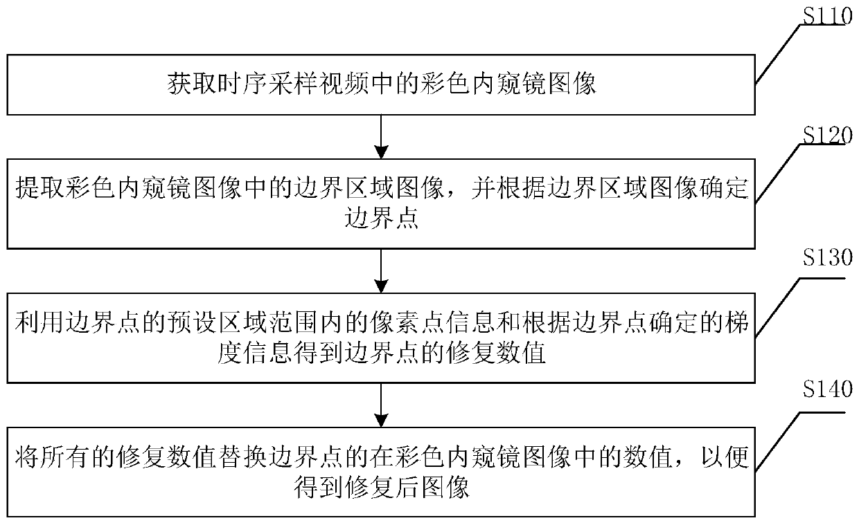
[0070] Please refer to figure 1 , figure 1 The flowchart of an image processing method provided by the embodiment of this application specifically includes:
[0071] S110. Acquire a color endoscopic image in the time-series sampling video.
[0072] In the field of endoscopy technology, the image in the time-sequential sampled video obtained by using time-series sampling has higher definition than the image in the video obtained through the Bayer template, and has higher brightness in the dyeing mode, but in the operation Since the movement of internal instruments or internal organs will produce colored borders, it is not conducive to the observation of medical personnel, thereby affecting the effect of surgery. Based on this, this embodiment provides an image processing method, which can solve the problem of image restoration of color boundaries caused by the movement of internal equipment or internal organs. The image is more intuitive and clear, and it is convenient for medical personnel to observe the restored image.
[0073] S120: Extract a boundary region image in the color endoscopic image, and determine a boundary point according to the boundary region image.
[0074] This embodiment does not limit the method of extracting the boundary area image, as long as the purpose of this embodiment can be achieved. It can be understood that the boundary area image includes multiple pixels, and further, the boundary point is determined based on the boundary area image. This embodiment does not limit the determination method of the boundary point, and the user can customize the setting.
[0075] In an achievable implementation, please refer to figure 2 , figure 2 The flow chart of extracting the color boundary region in another image processing method provided in this embodiment of the application. Specifically, extracting the boundary region image in the color endoscopic image and determining the boundary point according to the boundary region image includes:
[0076] S121: Extract a color boundary area of the color endoscopic image.
[0077] In an achievable implementation, extracting the color boundary area of the color endoscopic image includes:
[0078] Determine whether the R component of the pixel in the color endoscopic image is greater than the G component multiplied by the first preset multiple, or determine whether the R component of the pixel in the color endoscopic image is greater than the B component multiplied by the second preset Multiple; if yes, determine the pixel point whose R component is the first preset multiple of the G component or the pixel whose R component is the second preset multiple of the B component as the boundary area point, and obtain a boundary area point composed of all the boundary area points Color border area.
[0079] It is understandable that in the field of endoscopy technology, color endoscopy images have more hemoglobin, and therefore more red, resulting in a high content of R component. For a pixel in a color endoscopic image, when the R component is greater than the G component multiplied by the first preset multiple, it proves that the pixel is a boundary area point, or when the R component is greater than the B component multiplied by the second preset multiple When setting the multiple, it proves that the pixel is a boundary area point. At this time, all the boundary area points are determined by the threshold value, and the color boundary area composed of all the boundary area points is further obtained.
[0080] S122: Binarize and dilate the color boundary area to obtain an image of the boundary area.
[0081] The color boundary area is binarized to obtain a binarized image, that is, a black and white image, and the binarized image is expanded. Expansion is the process of merging all the background points in contact with the object into the object, expanding the boundary to the outside, and ensuring that the image of the boundary area is more complete.
[0082] In an achievable embodiment, performing the binarization and expansion processing on the color boundary area and obtaining the boundary area image further includes: performing an etching process. Corrosion is a process of eliminating boundary points and shrinking the boundary to the inside. The process of first corrosion and then expansion is called open operation. Used to eliminate small objects, separate objects at slender points, and smooth the boundaries of larger objects without changing their area significantly.
[0083] S123: Determine whether the gray value of the pixel in the boundary region image is 0.
[0084] S124. If yes, determine the pixel point with the gray value of 0 as the boundary point.
[0085] Among them, when the gray value of the pixel point in the boundary area image is 0, it proves that the point is a boundary point. It can be understood that the boundary area graphic includes a black part, that is, a pixel value of 255 and a white part of which the pixel value is 0, and a point with a pixel value of 0 is a boundary point. It is more efficient to determine the boundary point in this way.
[0086] S130: Obtain the repair value of the boundary point by using the pixel point information in the preset area of the boundary point and the gradient information determined according to the boundary point.
[0087] Among them, pixel point information includes contribution value and distance information, and gradient information includes x-direction gradient information and y-direction gradient information.
[0088] This embodiment does not limit the preset area range, which can be 5*5, 3*3, or 4*4, as long as it can achieve the purpose of this embodiment.
[0089] In an achievable implementation, please refer to image 3 , image 3 The flowchart for determining the repair value in another image processing method provided in this embodiment of the application, specifically, the boundary point is obtained by using the pixel point information within the preset area of the boundary point and the gradient information determined according to the boundary point The repaired values include:
[0090] S131. Determine the reference channel, and obtain a first image formed by dividing the first channel value by the reference channel data corresponding to the reference channel, and at the same time obtaining a second image formed by dividing the second channel value by the reference channel data.
[0091] This embodiment does not limit the reference channel, and may be any one of the R channel, G channel, and B channel. Wherein, the first channel value and the second channel value are both corresponding data in the color endoscopic image. When the reference channel is the R channel, in an achievable implementation, the first channel is the G channel, while the second channel is the B channel, and the first image is composed of data obtained by dividing the G channel data by the R channel data Image, the second image is the image formed by dividing the B channel data by the R channel data; in another achievable implementation, the first channel is the B channel, the second channel is the G channel, and the first image is The B channel data is divided by the R channel data to form an image, and the second image is the G channel data divided by the R channel data to form an image. When the reference channel is the G channel, in an achievable implementation, the first channel is the R channel, while the second channel is the B channel, and the first image is composed of data obtained by dividing the R channel data by the G channel data Image, the second image is an image formed by dividing the B channel data by the G channel data; in another achievable implementation, the first channel is the B channel, the second channel is the R channel, and the first image is The B channel data is divided by the G channel data to form an image, and the second image is the R channel data divided by the G channel data to form an image. When the reference channel is the B channel, in an achievable implementation, the first channel is the G channel, while the second channel is the R channel, and the first image is composed of the data obtained by dividing the G channel data by the B channel data Image, the second image is the image formed by dividing the R channel data by the B channel data; in another achievable implementation, the first channel is the R channel, the second channel is the G channel, and the first image is An image formed by dividing R channel data by B channel data, and the second image is an image formed by dividing G channel data by B channel data. Preferably, the reference channel is the G channel.
[0092] S132: Determine the first value of the first image and the second value of the second image by using the pixel point information in the boundary area image within the preset area range of all boundary points and the gradient information determined according to the boundary point.
[0093] In an achievable embodiment, the first value of the first image and the second value of the second image are determined by using pixel point information within a preset area of all boundary points and gradient information determined according to the boundary points, Including: determining multiple points that do not need to be repaired within the preset area of the boundary point; use the first preset algorithm to calculate the contribution value of each point that does not need to be repaired; based on the contribution value of each point that does not need to be repaired, according to the second preset The algorithm determines the value of the boundary point in order to obtain the first value of the first image and the second value of the second image; the first preset algorithm is ω=dir*abs(cosθ), and the second preset algorithm is
[0094] among them, Is the contribution value of the point that does not need to be repaired, Δx is the x distance between the point that does not need to be repaired and the boundary point, Δy is the y distance between the point that does not need to be repaired and the boundary point, gradx is the gradient information in the x direction, and grady is the gradient information in the y direction , I Know It is the value in the color endoscopic image that does not need to be repaired.
[0095] Among them, the points that do not need to be repaired are points other than the boundary points in the preset area, that is, in the boundary area image, the pixels within the preset area of the boundary point have a gray value of 255. The first preset algorithm is used to calculate the contribution value of each point that does not need to be repaired, and the second preset algorithm is used to obtain the value of the boundary point based on the contribution value, and finally the first value and the second value are obtained. For example, when the first image is an R/G image (an image formed by dividing the R channel data by the G channel data), the unrepaired points in the preset area of the boundary point b in the image are b1, b2, b3, for b1, ω 1 =dir 1 *abs(cosθ 1 ), Is the x distance between b1 and the boundary point, Is the y distance between b1 and the boundary point, I Know1 Is the R value of b1 in the color endoscopic image; for b2, ω 2 =dir 2 *abs(cosθ 2 ), Is the x distance between b2 and the boundary point, Is the y distance between b2 and the boundary point, I Know2 Is the R value of b2 in the color endoscopic image; for b3, ω 3 =dir 3 *abs(cosθ 3 ), Is the x distance between b3 and the boundary point, Is the y distance between b3 and the boundary point, I Know3 Is the R value of b3 in the color endoscopic image; the final value of the boundary point b in the first image is The above-mentioned processing is performed on the images of all the boundary points to obtain the values of all the boundary points of the first image. The values of all the boundary points constitute the first value of the first image, and similarly, the second value of the second image is obtained.
[0096] S133. Multiply the first value by the reference value corresponding to the reference channel to obtain the first repair value, and multiply the second value by the reference value corresponding to the reference channel to obtain the second repair value, so as to obtain the reference value, the first repair value and The repair value constituted by the second repair value.
[0097] In an achievable embodiment, when the first image is an R/G image (an image formed by dividing the R channel data by the G channel data), the first value is obtained. At this time, all the first values can be Take it as the R/G value, multiply it by the reference value G corresponding to the G channel of the reference channel, and get the R repair value, which is the first repair value; when the second image is a B/G image (the R channel data is divided by the G channel data to get When the image is composed of data), the second value is obtained. At this time, all the second values can be regarded as B/G values. Multiply the value by the reference value G corresponding to the reference channel G to obtain the B repair value, which is the second repair value. Finally, the repair value includes R repair value, reference value G and B repair value.
[0098] In another achievable embodiment, when the first image is an R/B image (an image formed by dividing the R channel data by the B channel data), the first value is obtained. At this time, all the first values It can be regarded as the R/B value, multiplied by the reference value B corresponding to the reference channel B channel, and the R repair value is the first repair value; when the second image is a G/B image (G channel data divided by B channel data to get The second value is obtained. At this time, all the second values can be regarded as G/B values, multiplied by the reference value B corresponding to the reference channel B, and the G repair value is the second repair value Finally, the repair value includes R repair value, G repair value, and reference value B.
[0099] In another achievable embodiment, when the first image is a G/R image (an image formed by dividing G channel data by R channel data), the first value is obtained. At this time, all the first values It can be regarded as the G/R value, multiplied by the reference value R corresponding to the R channel of the reference channel, and the G repair value is the first repair value; when the second image is a B/R image (the B channel data is divided by the R channel data to get The second value is obtained when the image is composed of data). At this time, all the second values can be regarded as B/R values, multiplied by the reference value R corresponding to the reference channel R channel, and the B repair value is the second repair value , Finally, the repair value includes the reference value R, G repair value, and B repair value.
[0100] S140: Replace all the repaired values with the values of the boundary points in the color endoscopic image, so as to obtain the repaired image.
[0101] Based on the above technical solution, this embodiment extracts the boundary area image of the color endoscopic image in the time-sampling video, and determines the boundary point, based on the pixel point information within the preset area of the boundary point and the gradient information determined by the boundary point Obtain the repair value so that the boundary point value in the original color endoscopic image can be replaced with the repair value to realize the restoration of the image, which can solve the image restoration problem of the color boundary caused by the movement of internal equipment or internal organs, and the image is more intuitive and clear. It is convenient for medical personnel to observe the repaired image.
[0102] Based on the above technical solution, this embodiment provides a specific image processing method, including:
[0103] 1. Obtain the color endoscopic image in the time-series sampling video.
[0104] 2. Determine whether the R component of the pixel in the color endoscopic image is greater than the G component multiplied by the first preset multiple, or determine whether the R component of the pixel in the color endoscopic image is greater than the B component multiplied by the second The preset multiple.
[0105] 3. If yes, determine the pixel points whose R component is the first preset multiple of the G component or the pixel points whose R component is the second preset multiple of the B component as the boundary area points, and obtain the boundary area points. Color border area.
[0106] 4. Binarize and dilate the color boundary area to obtain the boundary area image.
[0107] 5. Determine whether the gray value of the pixel in the border area image is 0.
[0108] 6. If yes, determine the pixel point with the gray value of 0 as the boundary point.
[0109] 7. Determine the reference channel as the G channel, get the first image that is the R/G image formed by dividing the R channel data by the G channel data, and at the same time get the second image formed by dividing the B channel data by the G channel data The image is the B/G image.
[0110] 8. Determine multiple points that do not need to be repaired within the preset area of the boundary point.
[0111] 9. Use the first preset algorithm to calculate the contribution value of each point that does not need to be repaired. The first preset algorithm is ω=dir*abs(cosθ), where, Δx is the x distance between the point that does not need to be repaired and the boundary point, Δy is the y distance between the point that does not need to be repaired and the boundary point, gradx is the gradient information in the x direction, and grady is the gradient information in the y direction.
[0112] 10. Based on the contribution value of each point that does not need to be repaired, the value of the boundary point is determined according to the second preset algorithm, so as to obtain the R/G value of the R/G image and the B/G value of the B/G image.
[0113] The second preset algorithm is ω is the contribution value of the point that does not need to be repaired, I Know It is the value in the color endoscopic image that does not need to be repaired.
[0114] 11. Multiply the R/G value by the G value corresponding to the G channel to obtain the R repair value, and multiply the B/G value by the G value corresponding to the G channel to obtain the B repair value, so as to obtain the G value, R repair value and B The repair value constituted by the repair value.
[0115] 12. Replace all the repaired values with the value of the boundary point in the color endoscopic image to obtain the repaired image.
[0116] The following describes an image processing device provided by an embodiment of the present application. The image processing device described below and the image processing method described above can be referred to each other. Figure 4 , Figure 4 The schematic diagram of the structure of an image processing device provided by an embodiment of this application includes:
[0117] The color endoscopic image acquisition module 100 is used to acquire the color endoscopic image in the time-series sampling video;
[0118] The boundary point extraction module 200 is used to extract the boundary area image in the color endoscopic image, and determine the boundary point according to the boundary area image;
[0119] The repair value determination module 300 is used to determine the repair value of the boundary point by using pixel point information within the preset area of the boundary point and the gradient information determined according to the boundary point, wherein the pixel point information includes contribution value, distance information, and gradient information Including x-direction gradient information, y-direction gradient information;
[0120] The repairing module 400 is used to replace all the repaired values with the values of the boundary points in the color endoscopic image to obtain the repaired image.
[0121] In some specific embodiments, the boundary point extraction module 200 includes:
[0122] The color boundary area extraction unit is used to extract the color boundary area of the color endoscopic image;
[0123] The boundary area image acquisition unit is used for binarizing and dilating the color boundary area to obtain the boundary area image;
[0124] The judging unit is used to judge whether the gray value of the pixel in the border area image is 0;
[0125] The boundary point determination unit is used to determine the pixel point with a gray value of 0 as the boundary point if it is.
[0126] In some specific embodiments, the color boundary region extraction unit includes:
[0127] A judging sub-unit for judging whether the R component of a pixel in the color endoscopic image is greater than the G component multiplied by a first preset multiple, or judging whether the R component of a pixel in the color endoscopic image is greater than the B component Multiply by the second preset multiple;
[0128] The color boundary area determining unit is configured to, if yes, determine the pixel points whose R component is a first preset multiple of G component or pixels whose R component is a second preset multiple of B component as boundary area points, and obtain The border area points constitute the color border area.
[0129] In some specific embodiments, the boundary region image acquisition unit further includes:
[0130] Corrosion sub-unit, used for corrosion treatment.
[0131] In some specific embodiments, the repair value determination module 300 includes:
[0132] The first image and the second image obtaining unit are used to determine the reference channel to obtain a first image composed of data obtained by dividing the first channel value by the reference channel data corresponding to the reference channel, and at the same time obtaining the second channel value divided by the reference channel A second image formed by data obtained from the data;
[0133] The first value and the second value obtaining unit are used to determine the first value of the first image and the second value of the second image by using the pixel point information within the preset area of all boundary points and the gradient information determined according to the boundary points Numerical value
[0134] The repair value determination unit is configured to multiply the first value by the reference value corresponding to the reference channel to obtain the first repair value, and multiply the second value by the reference value corresponding to the reference channel to obtain the second repair value, so as to obtain the reference value, A repair value composed of the first repair value and the second repair value.
[0135] In some specific embodiments, the first numerical value and the second numerical value obtaining unit include:
[0136] No need to repair point determining subunit, used to determine multiple points that do not need to be repaired within the preset area of the boundary point;
[0137] The contribution value determining subunit is used to calculate the contribution value of each point that does not need to be repaired by using the first preset algorithm;
[0138] The first value and the second value obtaining subunit are used to determine the value of the boundary point according to the second preset algorithm based on the contribution value of each point that does not need to be repaired, so as to obtain the first value of the first image and the first value of the second image Two-value
[0139] The first preset algorithm is ω=dir*abs(cosθ), and the second preset algorithm is
[0140] among them,
[0141] ω is the contribution value of the point that does not need to be repaired, Δx is the x distance between the point that does not need to be repaired and the boundary point, Δy is the y distance between the point that does not need to be repaired and the boundary point, gradx is the gradient information in the x direction, and grady is the gradient in the y direction Information, I Know It is the value in the color endoscopic image that does not need to be repaired.
[0142] Since the embodiment of the image processing device part corresponds to the embodiment of the image processing method part, please refer to the description of the embodiment of the image processing method part for the embodiment of the image processing device part, which will not be repeated here.
[0143] An electronic device provided by an embodiment of the present application will be introduced below. The electronic device described below and the image processing method described above may correspond to each other and refer to each other.
[0144] This embodiment provides an electronic device, including:
[0145] Memory, used to store computer programs;
[0146] The processor is used to implement the steps of the above-mentioned image processing method when the computer program is executed.
[0147] Since the embodiment of the electronic device part corresponds to the embodiment of the image processing method part, please refer to the description of the embodiment of the image processing method part for the embodiment of the electronic device part, which will not be repeated here.
[0148] The following introduces a computer-readable storage medium provided by an embodiment of the present application. The computer-readable storage medium described below and the image processing method described above may refer to each other correspondingly.
[0149] This embodiment provides a computer-readable storage medium on which a computer program is stored, and when the computer program is executed by a processor, the steps of the above-mentioned image processing method are implemented.
[0150] Since the embodiment of the computer-readable storage medium part corresponds to the embodiment of the image processing method part, please refer to the description of the embodiment of the image processing method part for the embodiment of the computer-readable storage medium part, which will not be repeated here.
[0151] The various embodiments in the specification are described in a progressive manner, and each embodiment focuses on the differences from other embodiments, and the same or similar parts between the various embodiments can be referred to each other. For the device disclosed in the embodiment, since it corresponds to the method disclosed in the embodiment, the description is relatively simple, and the relevant parts can be referred to the description of the method part.
[0152] Professionals can further realize that the units and algorithm steps of the examples described in the embodiments disclosed in this article can be implemented by electronic hardware, computer software, or a combination of both, in order to clearly illustrate the possibilities of hardware and software. Interchangeability, in the above description, the composition and steps of each example have been described generally in terms of function. Whether these functions are executed by hardware or software depends on the specific application and design constraints of the technical solution. Professionals and technicians can use different methods for each specific application to implement the described functions, but such implementation should not be considered beyond the scope of this application.
[0153] The steps of the method or algorithm described in combination with the embodiments disclosed herein can be directly implemented by hardware, a software module executed by a processor, or a combination of the two. The software module can be placed in random access memory (RAM), internal memory, read-only memory (ROM), electrically programmable ROM, electrically erasable programmable ROM, registers, hard disks, removable disks, CD-ROMs, or all areas in the technical field. Any other known storage media.
[0154] The above describes in detail an image processing method, image processing device, electronic equipment, and computer-readable storage medium provided by this application. Specific examples are used in this article to illustrate the principles and implementation of the application, and the description of the above examples is only used to help understand the methods and core ideas of the application. It should be pointed out that for those of ordinary skill in the art, without departing from the principles of this application, several improvements and modifications can be made to this application, and these improvements and modifications also fall within the protection scope of the claims of this application.
PUM


Description & Claims & Application Information
We can also present the details of the Description, Claims and Application information to help users get a comprehensive understanding of the technical details of the patent, such as background art, summary of invention, brief description of drawings, description of embodiments, and other original content. On the other hand, users can also determine the specific scope of protection of the technology through the list of claims; as well as understand the changes in the life cycle of the technology with the presentation of the patent timeline. Login to view more.
Similar technology patents
Double-layer display frame for vending machine commodities
Owner:安徽智佳信息科技有限公司
GAN (generative adversarial network) based image raindrop removal method
Owner:SUN YAT SEN UNIV
Lung function training device for respiratory medicine department
Owner:THE FIRST AFFILIATED HOSPITAL OF ANHUI MEDICAL UNIV
Template detecting device with clamping and lifting mechanism
Owner:徐州天骋智能科技有限公司
Display method of full patent texts based on computer display
Owner:CHANGZHOU BAITENG TECH
Classification and recommendation of technical efficacy words
- Easy to observe
- The image is clear and intuitive
Crack opening two-direction deformation monitoring structure and measurement method
Owner:NANCHANG HANGKONG UNIVERSITY
Visual soil freeze-thawing process test apparatus
Owner:NORTHWEST INST OF ECO-ENVIRONMENT & RESOURCES CAS
Roadbed deformation monitoring model device under traffic load and experimental method
Owner:HUBEI UNIV OF TECH
All-dimensional exhibition device for spatial model demonstrations
Owner:SOUTHWEST JIAOTONG UNIV
GAN (generative adversarial network) based image raindrop removal method
Owner:SUN YAT SEN UNIV