Supercharge Your Innovation With Domain-Expert AI Agents!

Marine automatic anti-swing high-voltage switch cabinet

A high-voltage switchgear, automatic technology, applied in the direction of substation/distribution device casing, etc., can solve the problems of complex structure of anti-swing device, reduced sensitivity of electronic components, low reliability of anti-swing device, etc., to achieve simple structure and high reliability. , to avoid the effect of random swinging

Active Publication Date: 2020-02-04
胜利油田海洋电气有限责任公司 +1
View PDF5 Cites 4 Cited by
  • Summary
  • Abstract
  • Description
  • Claims
  • Application Information

AI Technical Summary

Problems solved by technology

[0002] The main function of the switchgear is to open and close, control and protect the electrical equipment during the process of power generation, transmission, distribution and power conversion in the power system. Marine switchgear needs to consider the anti-swing performance of the switchgear, because the hull Swinging drives the switchgear to swing, which will easily loosen the internal circuit connection of the switchgear and affect the safe navigation of the ship. The existing marine anti-swing switchgear is realized by the cooperation of various electronic components, resulting in a complex structure of the anti-swing device. Swing easily reduces the sensitivity or failure of electronic components, resulting in low reliability of the anti-swing device, which cannot meet actual needs. Therefore, we have invented a marine automatic anti-swing high-voltage switchgear with a purely mechanical structure.

Method used


Image

  • Marine automatic anti-swing high-voltage switch cabinet
  • Marine automatic anti-swing high-voltage switch cabinet
  • Marine automatic anti-swing high-voltage switch cabinet

Examples


Embodiment Construction

[0014] In order to make the purpose, technical solutions and advantages of the embodiments of the present invention clearer, the technical solutions in the embodiments of the present invention will be clearly and completely described below in conjunction with the drawings in the embodiments of the present invention. Obviously, the described embodiments It is a part of embodiments of the present invention, but not all embodiments. Based on the embodiments of the present invention, all other embodiments obtained by persons of ordinary skill in the art without creative efforts fall within the protection scope of the present invention.

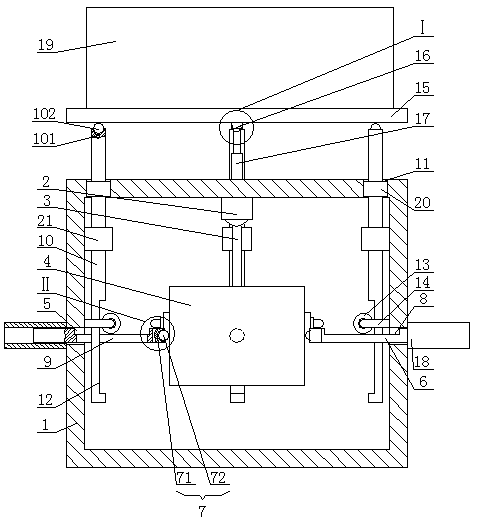
[0015] A marine automatic anti-swing high-voltage switch cabinet, as shown in the figure, includes a box body 1, the middle of the top of the box body 1 is fixedly connected to the upper end of the first spherical universal joint 2, and the lower end of the first spherical universal joint 2 is fixedly connected to the connecting rod 3, the lower e...


PUM


Abstract

The invention discloses a marine automatic anti-swing high-voltage switch cabinet, which comprises a box body. The middle of the top of the box body is fixedly connected with the upper end of a firstspherical universal joint; the lower end of the first spherical universal joint is fixedly connected with the upper end of a connecting rod; the lower end of the connecting rod is fixedly connected with the middle of the top side of a square heavy hammer; rectangular through grooves are formed in the front side, the rear side, the left side and the right side of the middle of the box body correspondingly; inserting plates are movably installed in the rectangular through grooves correspondingly and can only slide inwards or outwards along the corresponding rectangular through grooves correspondingly; the middles of the inner sides of the inserting plates are fixedly connected with the outer ends of columns correspondingly; and the spherical faces of the inner ends of the columns are in sliding contact fit with the corresponding sides of square heavy hammers. The marine automatic anti-swing high-voltage switch cabinet is simple in structure, ingenious in conception, capable of achievingautomatic anti-swing of the high-voltage switch cabinet through a simple pure mechanical structure, high in reliability, convenient to achieve, free of energy consumption, suitable for long-term marine operation, capable of meeting actual requirements and suitable for popularization.

Description

technical field [0001] The invention belongs to the field of electrical equipment, in particular to a marine automatic anti-swing high-voltage switchgear. Background technique [0002] The main function of the switchgear is to open and close, control and protect the electrical equipment during the process of power generation, transmission, distribution and power conversion in the power system. Marine switchgear needs to consider the anti-swing performance of the switchgear, because the hull Swinging drives the switchgear to swing, which will easily loosen the internal circuit connection of the switchgear and affect the safe navigation of the ship. The existing marine anti-swing switchgear is realized by the cooperation of various electronic components, resulting in a complex structure of the anti-swing device. Swing easily reduces the sensitivity or failure of electronic components, resulting in low reliability of the anti-swing device, which cannot meet the actual needs. Th...

Claims


Application Information

Patent Timeline
IPC IPC(8): H02B1/30
CPCH02B1/30
Inventor 许凤雪沈凤祥王霞牛长元高英全薛锋傅滨张堃
Owner 胜利油田海洋电气有限责任公司
Features
  • R&D
  • Intellectual Property
  • Life Sciences
  • Materials
  • Tech Scout
  • Unparalleled Data Quality
  • Higher Quality Content
  • 60% Fewer Hallucinations
Learn More