Isolation dimming circuit built by operational amplifier

A technology of optical lines and dimming signals, applied in the direction of electrical components, etc., can solve the problem that high-power lines cannot be satisfied at the same time, and achieve the effect of stable and clean DC level

A technology of optical lines and dimming signals, applied in the direction of electrical components, etc., can solve the problem that high-power lines cannot be satisfied at the same time, and achieve the effect of stable and clean DC level

CN110753428AActive Publication Date: 2020-02-04ZHEJIANG KAIYAO LIGHTING

Image

  • Isolation dimming circuit built by operational amplifier
  • Isolation dimming circuit built by operational amplifier
  • Isolation dimming circuit built by operational amplifier

Examples


Embodiment

[0029] The present invention proposes an isolated dimming circuit built by an operational amplifier, combined with figure 1 It includes a power supply input terminal 1, a high-power control circuit 2 and a power supply output terminal 4 connected in sequence, and a dimming signal conversion circuit 5 and a secondary side control circuit 3 are connected between the high-power control circuit 2 and the power supply output terminal 4. The optical signal conversion circuit 5 and the secondary control circuit 3 perform signal transmission through the first optocoupler, and the high-power control circuit 2 and the secondary control circuit 3 perform signal transmission through the second optocoupler.

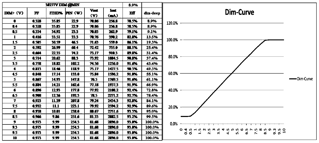
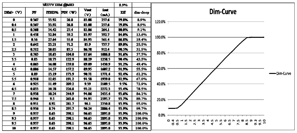
[0030]The dimming signal conversion circuit 5 receives the 0-10V dimming signal, transmits it to the secondary side control circuit 3 through the first optocoupler, the secondary side control circuit 3 processes the dimming signal, and feeds back to the high power control circuit 2 thr...


PUM


Abstract

The invention discloses a secondary side control isolation dimming circuit built by an operational amplifier. The secondary side control isolation dimming circuit comprises a power input end, a high-power control circuit and a power output end which are sequentially connected, wherein a dimming signal conversion circuit and a secondary side control circuit are connected between the high-power control circuit and the power output end; the dimming signal conversion circuit and the secondary side control circuit perform signal transmission through a first optical coupler; and the high-power control circuit and the secondary side control circuit perform signal transmission through a second optical coupler. The secondary side control isolation dimming circuit realizes the dimming function of input and output isolation and dimming signal and output isolation.

Description

technical field [0001] The invention relates to the technical field of dimming circuits, in particular to an isolated dimming circuit constructed by operational amplifiers. Background technique [0002] With the gradual decline of traditional thyristor dimming, more stable and reliable 0-10V dimming technology has begun to emerge. The corresponding laws and regulations have been gradually improved, and the safety regulations and standards have begun to require that the 0-10V dimmer needs to be safely isolated from the primary high voltage, and needs to be isolated from the power output SELV. [0003] At the same time, most of the 0-10V dimming solutions launched by major chip manufacturers focus on low-power flyback topology, or a single general-purpose chip for dimming signal reception. For complex high-power circuits such as LLC and LCC, no chip manufacturer has yet launched a complete set of 0-10V control solutions. There are also power supply manufacturers who directly...

Claims


Application Information

Patent Timeline
04 Feb 2020
Publication
CN110753428A
IPC
H05B47/10; H05B47/20
Inventors
许潇亮; 查丰盛