Trolley case having suspension structure and separated middle frame and rotating shaft

A trolley case and rotating shaft technology, applied in the directions of luggage, building structure, transportation and packaging, can solve the problems of easy deformation of zipper luggage, inflexible wheel seat movement, lack of shock absorption function, etc., to achieve structural stability and not easy to deform , The effect of saving labor assembly cost and light experience

Pending Publication Date: 2020-02-07
MERIT TECH FU JIAN CO LTD
View PDF0 Cites 1 Cited by
  • Summary
  • Abstract
  • Description
  • Claims
  • Application Information

AI Technical Summary

Problems solved by technology

[0003] At present, some trolley cases on the market lack the shock-absorbing function, and although the other part realizes shock-absorbing energy by setting springs, the assembly is complicated and the cost is high. In addition, ordinary zipper suitcases are easily deformed, resulting in inflexible movement of the wheel seat. The conventional mid-frame box is too heavy, which increases the weight of the luggage and requires greater force to drag. In addition, the conventional locks on the market require a lot of force to press after the luggage is full.

Method used


Image

  • Trolley case having suspension structure and separated middle frame and rotating shaft
  • Trolley case having suspension structure and separated middle frame and rotating shaft
  • Trolley case having suspension structure and separated middle frame and rotating shaft

Examples


Embodiment Construction

[0050] The embodiments of the present invention will be described in detail below with reference to the accompanying drawings, but the present invention can be implemented in many different ways defined and covered by the claims.

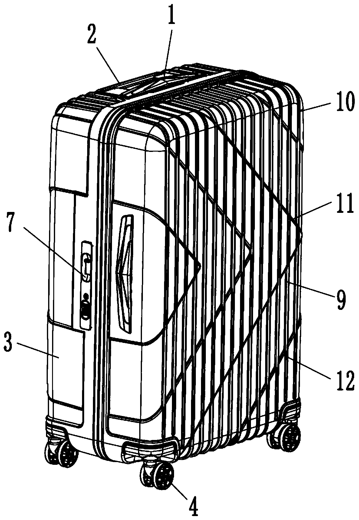
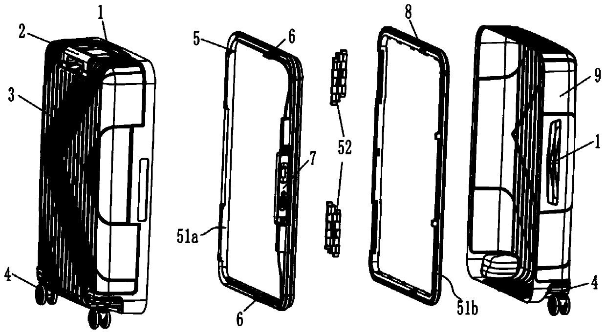
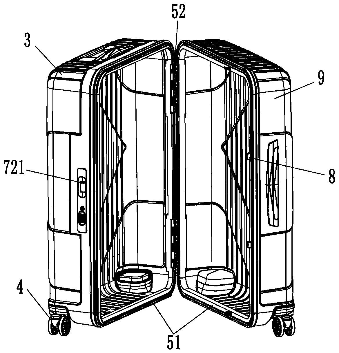
[0051] Refer below Figure 1 to Figure 22 The present invention is further described, as figure 1 , figure 2 , image 3 The shown suspension trolley case with middle frame and shaft separation includes pull rod 2, rear case 3, middle frame structure 5 and front case 9, middle frame structure 5 includes two groups of rotating shaft structures and a pair of middle frames 51, two The middle frame 51 is respectively a middle frame 1 51a and a middle frame 2 51b, wherein the middle frame 1 51a is connected with the rear shell 3, and the middle frame 2 51b is connected with the front shell 9, and the rotating shaft structure includes a pair of rotating shafts 52 and a mandrel, one of which The rotating shaft 52 is snapped and connected to the middle f...


PUM


Abstract

The invention provides a trolley case having a suspension structure and a separated middle frame and a rotating shaft. The trolley case comprises a pull rod, a rear shell, a middle frame structure anda front shell; the middle frame structure comprises a rotating shaft structure and a pair of middle frames, wherein one middle frame is connected with the rear shell, and the other middle frame is connected with the front shell; the rotating shaft structure comprises a pair of rotating shafts and a spindle, wherein one rotating shaft is clamped and connected to one middle frame, and the other rotating shaft is clamped and connected to the other middle frame; a pair of rotating shafts are movably connected with each other through the spindle; a pair of middle frames are locked by a linkage lock assembly; and suspension wheels are arranged at four corners of the bottom of the trolley case. The trolley case having the suspension structure and the separated middle frame and the rotating shaftprovided by the invention is not easy to deform, smoother in pulling and walking, reduces the strength of the human wrist, can be easily closed when filled with luggage, and provides a light experience.

Description

technical field [0001] The invention relates to a trolley case, in particular to a trolley case with a frame and rotating shaft separated in a shock-absorbing structure. Background technique [0002] The trolley case refers to the suitcase with a trolley and rollers. It is a must-have item for people to travel because of its convenient use. With the rapid development of the tourism industry, the growth of the travel market has brought consumers an increasing demand for trolley cases. For The trolley case business has brought new opportunities and challenges. [0003] At present, some trolley cases on the market lack the shock-absorbing function, and although the other part realizes shock-absorbing energy by setting springs, the assembly is complicated and the cost is high. In addition, ordinary zipper suitcases are easily deformed, resulting in inflexible movement of the wheel seat. The conventional mid-frame box is too heavy, which increases the weight of the luggage and r...

Claims


Application Information

Patent Timeline
Patent Type & Authority Applications(China)
IPC IPC(8): A45C5/14A45C5/04A45C13/00A45C13/10E05B63/14E05B65/52B60B33/00B60B33/04
CPCA45C5/14A45C5/045A45C13/00A45C13/10E05B65/52E05B63/143B60B33/0005B60B33/045B60B33/0026B60B33/0015B60B2200/45A45C13/1084A45C13/005A45C13/06E05B65/5253E05B35/105E05C9/041E05C9/1875E05B15/021A45C5/005A45C2005/037A45C5/143A45C2005/148A45C5/03A45C13/262
Inventor 侯议顺余群
Owner MERIT TECH FU JIAN CO LTD
Why Eureka
Try Eureka