Slow descending device

A technology of slow falling and objects, applied in the direction of life-saving equipment, building rescue, etc., can solve problems such as being entangled, hindering normal implementation, and low efficiency

Inactive Publication Date: 2020-02-07
王青松
View PDF1 Cites 0 Cited by
  • Summary
  • Abstract
  • Description
  • Claims
  • Application Information

AI Technical Summary

Problems solved by technology

There are two kinds of defects in this invention, one is that its working principle determines that it can only be used once by one person at the same time, and the efficiency is low; entangled, preventing the normal implementation of the function

Method used


Image

  • Slow descending device
  • Slow descending device
  • Slow descending device

Examples


Embodiment 1

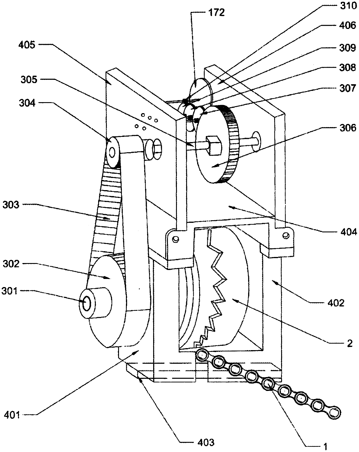
[0022] The power transmission line of the slow down device is: the transmission chain (1) meshes with the sprocket (2) to transmit power, and the sprocket (2) drives the large synchronous pulley (302) installed on the first main shaft (301) to rotate, and the large synchronous The belt pulley (302) transmits power to the small synchronous pulley (304) through the timing belt (303), and the small synchronous pulley (304) drives the bull gear (306) and bull gear (306) installed on the second main shaft (305). 306) transmits power to double-layer gear (307), double-layer gear (307) transmits power to double-layer gear (308), double-layer gear (308) transmits power to double-layer gear (309), double-layer gear (309) transmits the power to the pinion (310), the pinion (310) drives the shaft (171) to rotate, and the shaft (171) drives the metal disc (172) mounted thereon to rotate, and the metal disc (172 ) continuously cuts the horseshoe magnet (173) fixed on the frame by rotating,...

Embodiment 2

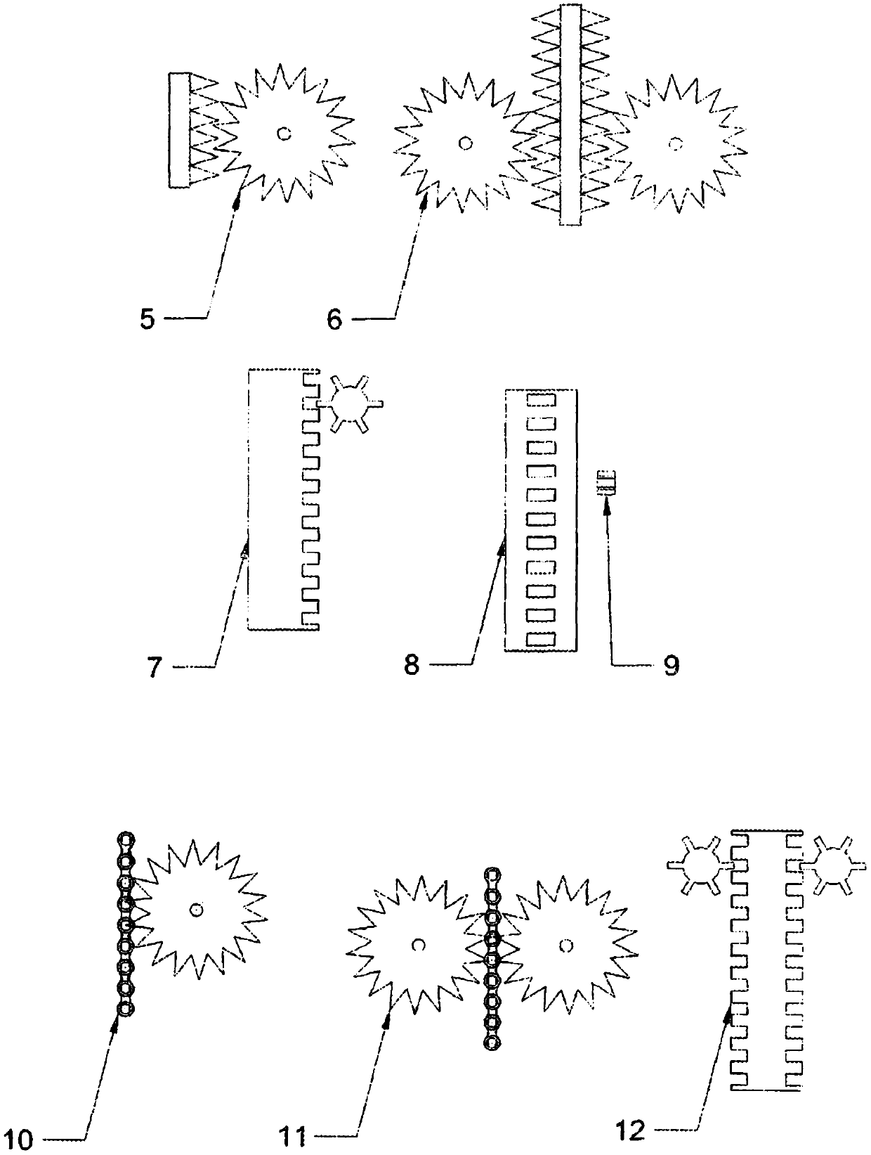
[0025] The meshing method can be adopted as figure 2 Multiple ways shown. Among them (5) the toothed belt meshes with the gear on one side; (6) the toothed belt meshes with the gear on both sides; (7) the rectangular grooved belt meshes with the polygonal wheel on one side; (8) the rectangular grooved belt is in the middle; (9) ) The top view of the polygonal wheel; (10) The transmission chain meshes with the sprocket on one side; (11) The transmission chain meshes with the sprocket on both sides; (12) The rectangular groove belt meshes with the polygonal wheel on both sides.

Embodiment 3

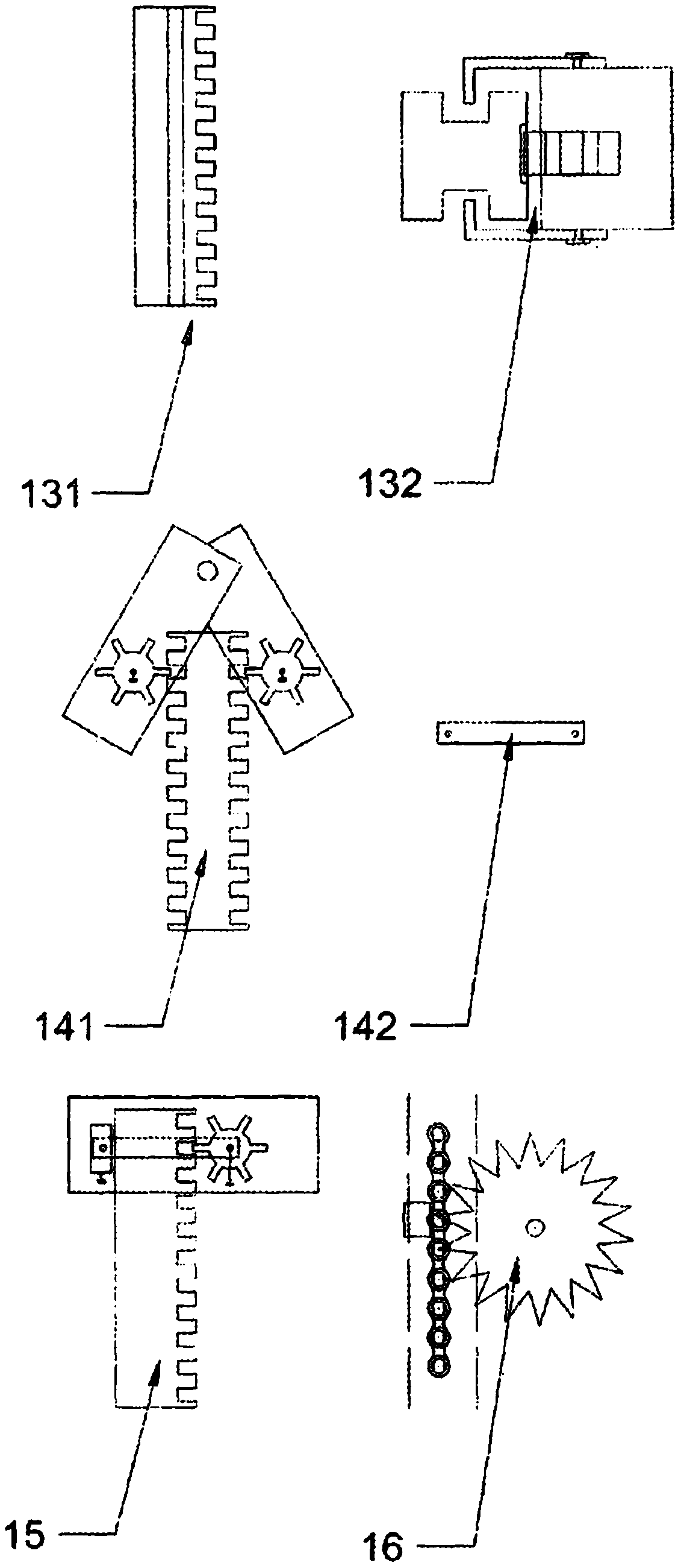
[0027] Rack positioning methods can be used such as image 3 Multiple ways shown. Wherein (131) is the strip structure with groove on the side, (132) is the meshing positioning mode of the aforementioned strip structure; (141) is the engagement positioning mode of the rectangular grooved belt and the polygonal wheel bilateral sides, and (142) is the positioning mode of the aforementioned positioning mode Movable fixed parts; (15) the positioning method of rectangular groove with side engagement; (16) the positioning method for the transmission chain and sprocket engagement figure 1 The targeting method in .


PUM


Abstract

The invention discloses a slow descending device, more particularly relates to a single-way type slow descending device which can be used for descending multiple persons at a time and belongs to the field of high-rise rescue. Two defects exist in an existing slow descending device, one defect is that the work principle of the slow descending device determines that the slow descending device can beonly used by one person once at the same time, and efficiency is low; and the other defect is that when a fire happens, if multiple persons use multiple sets of slow descending devices, the lower ends of ropes are likely to be twisted and entangled together, and normal implementation of the function is hindered. By means of the slow descending device, a rack is used for limiting the distance of rotating engagement, the falling energy is transmitted to an energy consumption mechanism, a whole composed of the rack, the energy consumption mechanism and a transmission mechanism can be engaged with a path to slide on the designated path, and therefore the function of conducting descending along the designated path is achieved. A single descending path is adopted in the structure, and the problems of twisting and entangling of the ropes in traditional design are solved. A structure capable of clamping the path is designed on the rack of the structure, multiple pieces of equipment can be clamped at the same time on the path, and the purpose of descending multiple persons at the same time is achieved.

Description

technical field [0001] The invention relates to a slow-descent device, more specifically, to a single-path slow-descent device capable of slow-downing multiple people at one time, and belongs to the field of high-rise rescue. Background technique [0002] With the advancement of the times and the development of technology, more and more people have moved into high-rise residential areas. High-rise buildings are a double-edged sword. On the one hand, they save scarce land resources. It has the characteristics of fast fire spread and slow evacuation of personnel. The Chinese utility model patent with the patent number CN207356383U discloses "a high-rise escape slow descender". The inner gear ring, the planetary gear and the sun gear are connected by transmission, the rope drives the cylinder to rotate, and the central shaft is driven by the inner gear ring-planetary gear-sun gear, and the rope drives the cylinder And the inner gear ring rotates once, and the planetary gear a...

Claims


Application Information

Patent Timeline
Patent Type & Authority Applications(China)
IPC IPC(8): A62B1/06
CPCA62B1/06
Inventor 王青松
Owner 王青松
Why Eureka
Try Eureka