cutting machine head

A technology of cutting machine and machine head, which is applied in the cutting of textile materials, textiles and papermaking, metal processing, etc. It can solve the problems of no vibration damping device, large noise, and no installation, so as to prolong life, reduce noise, The effect of reasonable structural design

Active Publication Date: 2015-08-12
HANGZHOU ECHO SCI TECH
View PDF15 Cites 0 Cited by
  • Summary
  • Abstract
  • Description
  • Claims
  • Application Information

AI Technical Summary

Problems solved by technology

[0005] Chinese Patent No. 201110064074.8 discloses an invention patent named "cutting device", which includes a workbench, an upper cutter cylinder fixedly installed on the workbench, and is connected to the upper cutter cylinder through a first floating joint The drive rod also includes the lower cutter cylinder. Although the present invention is simple in structure, it does not have a damping device, which will generate a lot of noise, and there is no sharpening device and tool deviation correction device, so it still has the above defects; Chinese Patent No. 200910264365.4 discloses an invention patent named "cutting machine", which includes a frame support rod, which is fixed on the top plate, and the bottom plate is provided with rollers, which are installed in the guide rails. Although the structure of the invention Simple, but there is no mechanism that can reduce noise and reduce deviation, so it still has the above defects

Method used


Image

  • cutting machine head
  • cutting machine head
  • cutting machine head

Examples


Embodiment Construction

[0032] Below in conjunction with accompanying drawing and embodiment the utility model is described further.

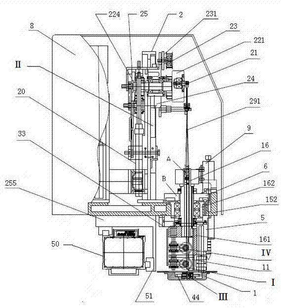
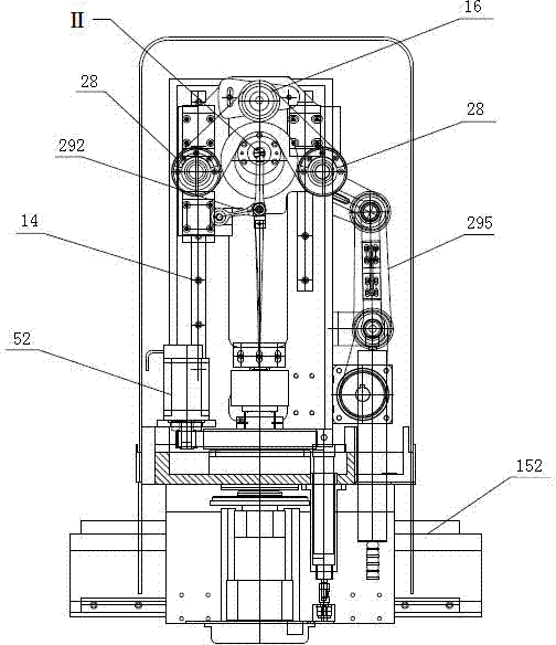
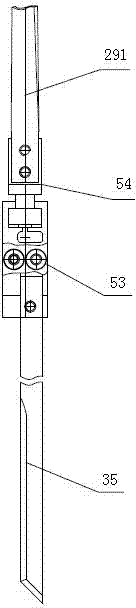
[0033] see Figure 1 to Figure 16 , The head of the cutting machine in this embodiment includes a material pressing and knife feeding device I, a vibration damping device II, a tool deviation correction device III and a knife sharpening device IV.

[0034] The sharpening device IV in this embodiment is located at the upper part of the machine head, the tool deviation correction device III, the sharpening device IV and the pressing and knife-feeding device I are located at the lower part of the whole machine, and the pressure plate 1 on the pressing and knife-feeding device I The elastic arm 34 is connected, and the tool deviation correction device III is arranged on the elastic arm 34. The material pressing and knife-feeding device I is connected with the machine head horizontal fixing frame 152 on the head of the whole machine through the rotating shaft, and the shar...


PUM


Abstract

The invention relates to a machine head of a cutting machine, belongs to a component of the cutting machine, and is applied to the cutting field. The machine head of the cutting machine comprises a pressing and feeding device and a cutter grinding device, and is characterized by further comprising a cutter deviation-correcting device and a shock absorption device. The cutter deviation-correcting device comprises a guide wheel frame, a pressing wheel and a position sensor on an elastic arm, wherein a pressing disc is provided with the guide wheel frame, and the guide wheel frame is provided with the pressing wheel and a rear pressing wheel. The shock absorption device comprises a servo motor, a first synchronous belt wheel group and a vibration shaft, wherein the servo motor is arranged on a machine head vertical fixing frame through a motor fixing seat, and the vibration shaft is connected on a machine head seat. Due to the fact that the cutter deviation-correcting device and the shock absorption device are arranged on the machine head, the deviation between top-layer material and bottom-layer material is well controlled, and noise in the cutting process is lowered.

Description

technical field [0001] The utility model relates to a machine head, in particular to a cutting machine head, which belongs to a part of the cutting machine and is applied in the field of cutting. Background technique [0002] At present, when cutting high-layer fabrics, when the actual cutting thickness reaches more than 50mm, one of the main problems that arises is that there is a deviation in size between the top-layer fabric and the bottom-layer fabric, which directly affects the product quality. Through experiments, it is found that this phenomenon is caused by the torsion of the knife caused by the extrusion of the fabric against the knife surface during cutting, and if the deviation is not corrected in time, it may even cause the breakage of the knife in severe cases. [0003] In some existing cutting machines, the motor is fixed on the pallet that moves up and down, and the eccentric wheel is directly connected to the motor shaft, and the vibration force when the moto...

Claims


Application Information

Patent Timeline
Patent Type & Authority Patents(China)
IPC IPC(8): B26D1/12B26D7/26B26D5/08B26D7/12D06H7/00
Inventor 方云科张东升
Owner HANGZHOU ECHO SCI TECH
Why Eureka
Try Eureka