A forming method and forming device for a slender C-shaped cross-section sheet metal part

A forming method and technology of sheet metal parts, which are applied in the field of aviation parts processing, can solve problems such as difficult one-time forming, difficult demoulding of parts, and slender dies that are difficult to ensure rigidity, so as to improve forming efficiency and quality, and solve processing deformation problems , the effect of reducing the amount of manual work

Active Publication Date: 2022-04-08
CHENGDU AIRCRAFT INDUSTRY GROUP
View PDF5 Cites 0 Cited by
  • Summary
  • Abstract
  • Description
  • Claims
  • Application Information

AI Technical Summary

Problems solved by technology

[0003] Existing technical solutions: the web surface of the part is mostly a torsion hyperboloid, and the two flanges of the part are large closed angles, and it is difficult to form it at one time when a mold is used
Due to the small geometric size of the cross-section of the part, if the stamping die is used for forming in the first process, the die is slender and it is difficult to ensure sufficient rigidity. Even if the rigidity of the die is sufficient, the part can only be formed into a U-shaped intermediate transition shape. The closed-angle flange still cannot be formed in place by the mold; in the second process, when the closed-angle flange of the part is manually formed, the part is difficult to demould due to the closed-angle wrapping after forming

Method used


Image

  • A forming method and forming device for a slender C-shaped cross-section sheet metal part
  • A forming method and forming device for a slender C-shaped cross-section sheet metal part
  • A forming method and forming device for a slender C-shaped cross-section sheet metal part

Examples


Embodiment 1

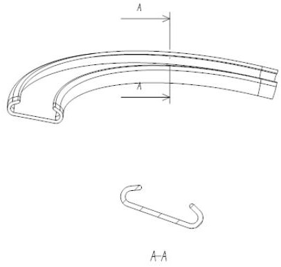
[0036] A method for forming a slender C-shaped cross-section sheet metal, characterized in that the forming method comprises the following steps:

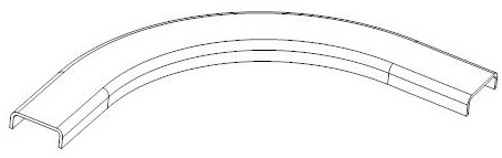
[0037] A. U-shaped transition shape of preformed parts;

[0038] B. When using, position the part unfolded blank on the mold body with the part positioning pin, and use the mold positioning pin to position the cover plate and the mold body;

[0039] C. After the installation is completed, the U-shaped preformed shape of the part is flexibly pressed and formed by a rubber bag hydroforming machine;

[0040] D. Use manual forming dies to form the two closed corners of the parts;

[0041] E. Complete the final shape of the parts and achieve smooth pick-up.

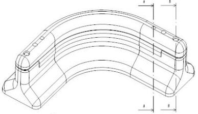
[0042] A forming device for thin and long C-shaped sheet metal parts, characterized in that it includes: a mold body 1 and a base 7, and the mold body 1 includes: a cover plate 2, a part positioning pin 3, a mold positioning pin 4 and parts The preformed shape 5, the base 7 incl...

Embodiment 2

[0044] A method for forming a slender C-shaped cross-section sheet metal, characterized in that the forming method comprises the following steps:

[0045] A. U-shaped transition shape of preformed parts;

[0046] B. When using, position the part unfolded blank on the mold body with the part positioning pin, and use the mold positioning pin to position the cover plate and the mold body;

[0047] C. After the installation is completed, the U-shaped preformed shape of the part is flexibly pressed and formed by a rubber bag hydroforming machine;

[0048] D. Use manual forming dies to form the two closed corners of the parts;

[0049] E. Complete the final shape of the parts and achieve smooth pick-up.

[0050] The detailed steps of step A are as follows: forming the intermediate transitional shape of the part with the rubber hydroforming die, making the bent edges at the closed corners at both ends of the cross section of the part vertically downward, and making the mold body U-...

Embodiment 3

[0053] A method for forming a slender C-shaped cross-section sheet metal, characterized in that the forming method comprises the following steps:

[0054] A. U-shaped transition shape of preformed parts;

[0055] B. When using, position the part unfolded blank on the mold body with the part positioning pin, and use the mold positioning pin to position the cover plate and the mold body;

[0056] C. After the installation is completed, the U-shaped preformed shape of the part is flexibly pressed and formed by a rubber bag hydroforming machine;

[0057] D. Use manual forming dies to form the two closed corners of the parts;

[0058] E. Complete the final shape of the parts and achieve smooth pick-up.

[0059] The detailed steps of step A are as follows: forming the intermediate transitional shape of the part with the rubber hydroforming die, making the bent edges at the closed corners at both ends of the cross section of the part vertically downward, and making the mold body U-...


PUM


Abstract

The invention belongs to the field of aviation parts processing, and specifically relates to a processing method for slender strip parts. It is characterized in that the forming method includes the following steps: A. pre-forming the U-shaped transition shape of the part; B. unfolding the part for the blank when using The positioning pin is positioned on the mold body, and the cover plate and the mold body are positioned with the mold positioning pin; C. After the installation is completed, the U-shaped pre-formed shape of the part is flexibly packaged with a rubber bag hydroforming machine; D. The manual forming mold is used Bend at the two closed corners of the formed part; E. Complete the final shape of the part and realize the smooth pick-up, a forming device for thin and thin C-shaped cross-section sheet metal parts, which is characterized in that it includes: a mold body and a base, the The mold body includes: a cover plate, a part positioning pin, a mold positioning pin and a preformed shape of a part, and the base includes: a mushroom pin, a part, a first core block, a second core block and a third core block.

Description

technical field [0001] The invention belongs to the field of aviation parts processing, and in particular relates to a processing method for slender strip parts. Background technique [0002] There is a complex C-shaped cross-section sheet metal part in the boarding gate of a civil aircraft. The cross-sectional width generally does not exceed 20mm, and the height generally does not exceed 6.5mm. The web is a hyperboloid, and the length is generally more than 500mm, and the longest can reach 3000mm. [0003] The prior art scheme: the web surface of the part is mostly a torsion hyperboloid, and the two flanges of the part are large closed angles, and it is also difficult to form at one time when a mold is used. Due to the small geometric size of the cross-section of the part, if the first process is formed by a stamping die, the die is slender and it is difficult to ensure sufficient rigidity. Even if the rigidity of the die is sufficient, the part can only be formed into a U-...

Claims


Application Information

Patent Timeline
Patent Type & Authority Patents(China)
IPC IPC(8): B21D53/92B21D37/10
CPCB21D53/92B21D37/10
Inventor 王晓康石章虎何万飞
Owner CHENGDU AIRCRAFT INDUSTRY GROUP
Why Eureka
Try Eureka