Unlock instant, AI-driven research and patent intelligence for your innovation.

Controlling method and device for minimizing standing time of casting blank

A technology of residence time and control method, applied in the field of continuous casting, which can solve the problems of significant radiation heat dissipation, inability to achieve optimization, and inability to realize the residence time of slabs.

Active Publication Date: 2020-02-07
CONTINUOUS CASTING TECH ENG OF CHINA
View PDF12 Cites 2 Cited by
  • Summary
  • Abstract
  • Description
  • Claims
  • Application Information

AI Technical Summary

Problems solved by technology

[0006] The traveling speed of the slab in the continuous casting section and the cutting section is completely limited by the casting speed of the casting machine, which is generally less than 4.0m / min, while the speed of the transition roller table section and the conveying roller table section is very high, which can reach 50-300m / min. It is necessary to optimize the cut-to-length slab in the continuous casting section and the cutting section; at the same time, the temperature of the cut-to-size slab in the continuous casting section and the cutting section is relatively high, generally above 1000°C, and the radiation heat dissipation is significant, which can reach 30°C / Min above, but the existing technology can not realize the optimization of this area
In addition, the design of the cutting stroke of the existing cutting transposition only considers that the cast slab can be cut off at the maximum casting speed of the casting machine, and the cutting process is fixed: after the cutting is completed, the cutting device returns to the starting position; After the initial position is equal to the fixed length, clamp the billet and start cutting; until the cutting is completed
Regardless of design or actual operation, under different pouring speeds, the cutting starts from the cutting start position, and the function of reducing the residence time of the slab in the casting stream under different casting speeds cannot be realized

Method used


Image

  • Controlling method and device for minimizing standing time of casting blank
  • Controlling method and device for minimizing standing time of casting blank
  • Controlling method and device for minimizing standing time of casting blank

Examples


Embodiment Construction

[0046] In the following description, for purposes of explanation, numerous specific details are set forth in order to provide a thorough understanding of one or more embodiments. It may be evident, however, that these embodiments may be practiced without these specific details. Specific embodiments of the present invention will be described in detail below in conjunction with the accompanying drawings.

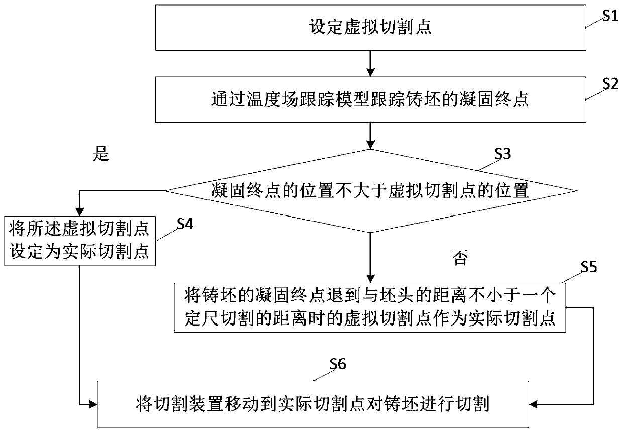
[0047] figure 2It is a schematic diagram of the flow chart of the control method for minimizing the residence time of the slab in the strand according to the present invention, such as figure 2 As shown, the control method includes:

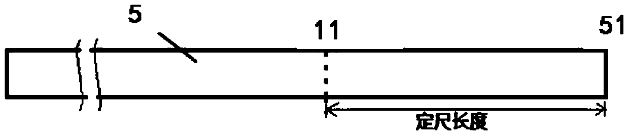
[0048] Step S1, setting virtual cutting point 11, such as image 3 As shown, the virtual cutting point is set at a distance of a predetermined length from the billet head 51 of the uncut billet 5 along the direction of the billet, and the virtual cutting point moves along with the billet head of the uncut billet As for the changing virtual ...


PUM


Abstract

The invention provides a controlling method and device for minimizing the standing time of a casting blank. The method comprises the steps that a virtual cutting point is set, and the virtual cuttingpoint is set at the specified length distance of a blank head of the casting blank which is not cut in the reverse direction of the casting blank; the solidification end point of the casting blank istracked through a temperature field tracking model; whether the solidification end point of the casting blank which is not cut is not larger than the virtual cutting point position or not is judged; if yes, the virtual cutting point is set as an actual cutting point; if not, the solidification end point of the casting blank is drawn back to a virtual cutting point where the distance between the solidification end point and the blank head is not smaller than the specified cutting distance and set as the actual cutting point; and a cutting device is moved to the actual cutting point to cut the casting blank. According to the control method device, the standing time of the casting blank in casting flow is minimized.

Description

technical field [0001] The invention relates to the technical field of continuous casting, and more specifically, relates to a control method and device for minimizing the residence time of a slab in a casting stream. Background technique [0002] The direct rolling technology saves the heating furnace process between continuous casting and steel rolling, saves energy consumption and pollutant emissions, and brings significant energy saving and emission reduction effects, thereby reducing the cost per ton of steel and having significant direct economic benefits. [0003] To realize the direct rolling technology, the first thing is to ensure that the temperature of the slab before reaching the rolling mill is high enough to meet the high temperature rolling requirements. In order to achieve this goal, the existing technology has been greatly improved, such as increasing the pouring speed of continuous casting, increasing the cutting speed, increasing the speed of the roller t...

Claims


Application Information

Patent Timeline
Patent Type & Authority Applications(China)
IPC IPC(8): B22D11/16
CPCB22D11/163
Inventor 钱亮韩占光高文星谢长川周干水
Owner CONTINUOUS CASTING TECH ENG OF CHINA
Features
  • R&D
  • Intellectual Property
  • Life Sciences
  • Materials
  • Tech Scout
  • Unparalleled Data Quality
  • Higher Quality Content
  • 60% Fewer Hallucinations
Learn More