Positioning structure and method for surface layer inserts

A positioning structure and positioning method technology, which is applied in the field of preparation of composite materials with surface inserts, can solve the problems of inability to achieve accurate positioning of inserts, inaccurate compensation effects, and increased weight of composite materials, achieving good promotion and application value and improving pass rate and the effect of improving production efficiency

Active Publication Date: 2020-02-07
AEROSPACE INST OF ADVANCED MATERIALS & PROCESSING TECH
View PDF4 Cites 0 Cited by
  • Summary
  • Abstract
  • Description
  • Claims
  • Application Information

AI Technical Summary

Problems solved by technology

However, for the positioning of surface metal inserts in composite structural parts, conventional mold positioning pins are used, and it is impossible to adjust the position deviation of inserts during mold loading; especially for multiple inserts, accurate positioning is required from different normal directions During operation, this method cannot achieve accurate positioning of the insert, and deviations are prone to occur
In order to make up for the position deviation in the molding process, the size of the metal parts is generally increased in the existing process, and the compensation effect is not accurate enough. However, increasing the size of the metal parts will increase the weight of the composite material, which cannot meet the existing weight reduction, Design Requirements for Precise Positioning

Method used


Image

  • Positioning structure and method for surface layer inserts
  • Positioning structure and method for surface layer inserts
  • Positioning structure and method for surface layer inserts

Examples


Embodiment

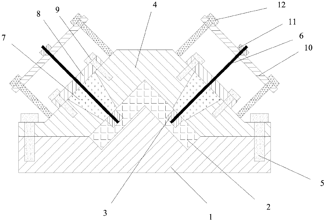
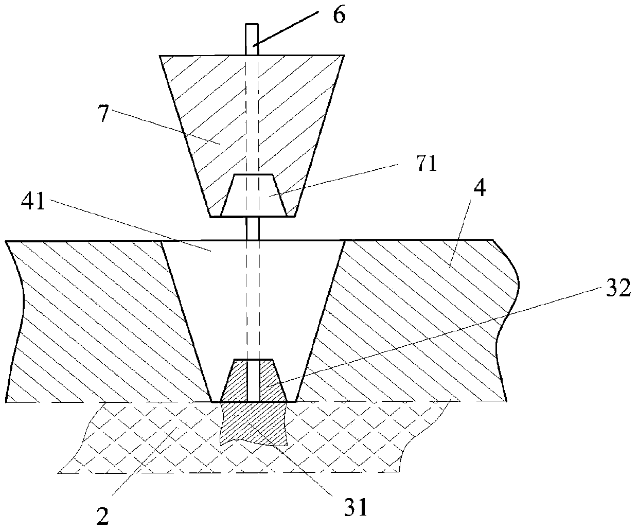
[0052] Carry out accurate positioning of 10 outer layer metal inserts 3 in an L-shaped cross-section composite quilted beam structure 2. The length of the L-shaped cross-section quilted beam structure is 1000 mm, and each side of the L-shaped cross-section has 5 metal inserts on the outer layer.

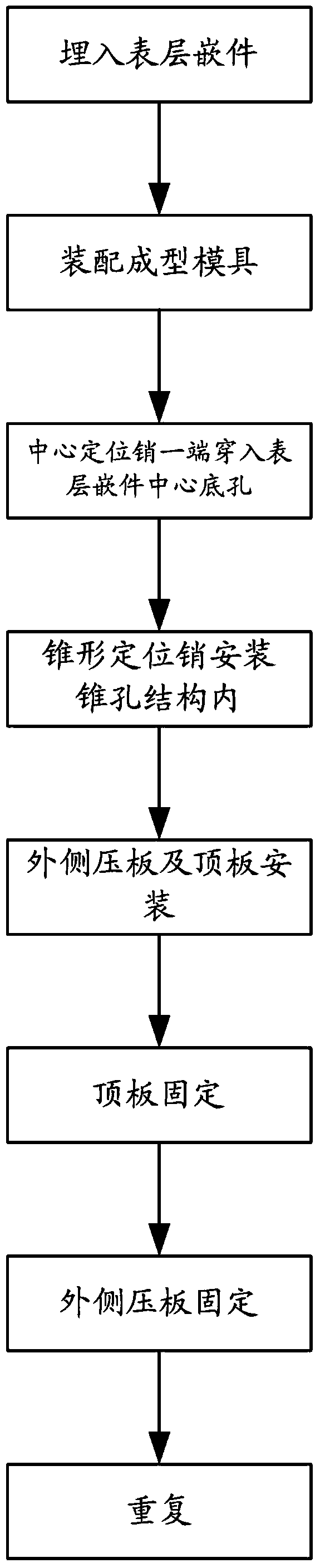
[0053] Manually lay carbon fiber plies layer by layer in the lower half-mold 1 of the forming mold to prepare an L-shaped cross-section quilted beam prefabricated body. The fiber plies whose outer layer needs to be embedded with metal inserts need to be pre-drilled according to the designed position (10 holes in total) ;

[0054] After the fiber layup is complete, metal inserts are placed in the openings of the layup;

[0055] Assemble the upper half-molds 1 and 4, align the upper and lower half-molds and insert the positioning pin 5, install the fastening bolts to ensure that the upper and lower half-molds are closed in place, and the gap between the joint surfaces is less than 0.05...


PUM


Abstract

The invention provides a positioning structure and method for surface layer inserts. The positioning structure comprises the surface layer inserts, a center positioning pin, a taper hole structure, ataper positioning pin, an outer side pressing plate structure and a top plate structure. According to the positioning structure and method, the structure weight reduction target can be achieved to themaximum extent, and deviation adjustment and accurate positioning of the inserts in different normal directions can be achieved one by one in the one-time forming process of components.

Description

technical field [0001] The invention relates to a positioning structure and a positioning method of a surface insert, and belongs to the technical field of preparation of composite materials containing surface inserts. Background technique [0002] Due to its outstanding features of light weight, high strength and strong designability, composite materials have been widely used in military and civilian fields since their appearance in the mid-1960s, such as aerospace, weaponry, sports and leisure, infrastructure facilities, automobile and shipbuilding industries , biological engineering, etc., especially in various weapons and equipment (such as military aircraft, missiles, etc.), it plays a vital role in promoting lightweight and high performance. The use of advanced composite materials in aerospace structures can reduce weight by 20-30%, which is an effect that other advanced technologies cannot achieve. Therefore, composite materials are increasingly used in the aerospace ...

Claims


Application Information

Patent Timeline
Patent Type & Authority Applications(China)
IPC IPC(8): B29C70/68B29C33/12B29K705/00
CPCB29C33/126B29C70/681B29K2705/00
Inventor 田正刚王国勇柳晓辉朱八一狄海笑
Owner AEROSPACE INST OF ADVANCED MATERIALS & PROCESSING TECH
Why Eureka
Try Eureka