High-performance hydraulic braking main cylinder

A hydraulic braking, high-performance technology, applied in the direction of hydraulic braking transmission, etc., can solve the problems of low flow and oil pressure, not optimal state, insufficient braking efficiency, etc., to improve braking efficiency, increase effect of stress

Inactive Publication Date: 2020-02-07
浙江奔腾智能制动系统有限公司
View PDF5 Cites 0 Cited by
  • Summary
  • Abstract
  • Description
  • Claims
  • Application Information

AI Technical Summary

Problems solved by technology

However, these two states are relative states in the process of the piston moving forward. The existing method can only make a trade-off between the two to obtain a balanced state, so that both can be taken into account, but neither is the best. good condition
And such a setting makes the early stage of braking, because the pressure in the brake chamber is small, so that the flow rate and oil pressure in the early stage are relatively low, and the braking efficiency is not high enough.

Method used


Image

  • High-performance hydraulic braking main cylinder
  • High-performance hydraulic braking main cylinder
  • High-performance hydraulic braking main cylinder

Examples


Embodiment Construction

[0031] The following will clearly and completely describe the technical solutions in the embodiments of the present invention with reference to the accompanying drawings in the embodiments of the present invention. Obviously, the described embodiments are only some, not all, embodiments of the present invention. Based on the embodiments of the present invention, all other embodiments obtained by persons of ordinary skill in the art without creative efforts fall within the protection scope of the present invention.

[0032] Refer as follows Figure 1-3 The present invention is described:

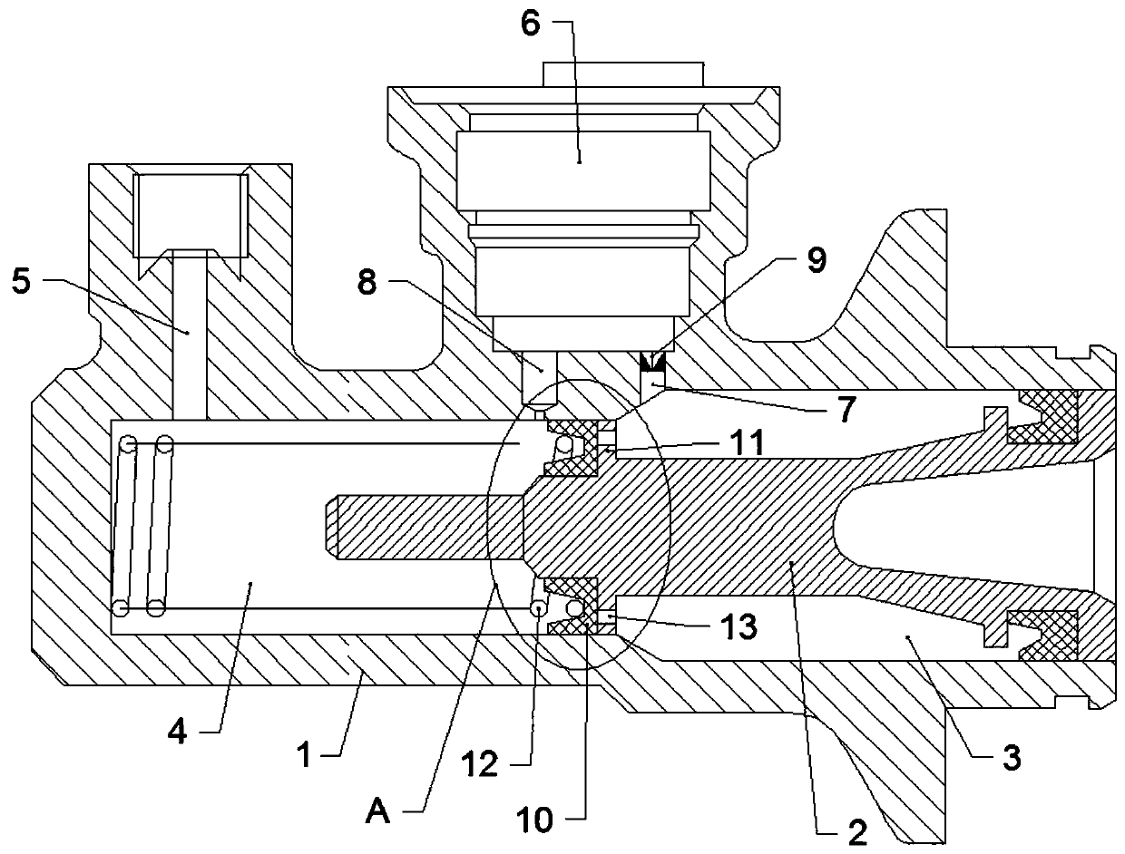
[0033] A high-performance hydraulic brake master cylinder, including a cylinder body 1, a piston 2 is arranged in the cylinder body 1, a brake chamber 3 and an oil inlet chamber 4 are formed between the piston 2 and the cylinder body 1, and the brake chamber 3 is located on the front side of the oil inlet chamber 4.

[0034] The front end of the cylinder block 1 is provided with an oil outl...


PUM


Abstract

The invention provides a high-performance hydraulic braking main cylinder. The high-performance hydraulic braking main cylinder comprises a cylinder body. A piston is arranged in the cylinder body, abraking cavity and an oil inflow cavity are formed between the piston and the cylinder body, and the braking cavity is located in the front side of the oil inflow cavity. An oil outlet communicating with the braking cavity is formed in the front end of the cylinder body. An oil cup hole is formed in the rear end of the cylinder body, an oil inlet communicating with the oil inflow cavity is formedin the bottom of the oil cup hole, and an oil overflow hole communicating with an inner cavity of the cylinder body is formed in the bottom of the oil cup hole. A first one-way valve only allowing oilin the oil cup hole to enter the oil inflow cavity is arranged in the oil inlet. An annular rubber leather bowl is arranged on the portion, between the braking cavity and the oil inflow cavity, of the piston, an annular boss is arranged on the portion, on the rear side of the rubber leather bowl, of the piston, and the boss abuts against the rear side face of the rubber leather bowl and is in sealing fit with the rear side face of the rubber leather bowl. A spring is arranged in the braking cavity, the front end of the spring abuts against the front end of the cylinder body, and the rear endof the spring stretches into the rubber leather bowl and abuts against the rubber leather bowl. First oil holes communicating with the front side and the rear side of the boss are formed in the boss,and second oil holes communicating with the front side and the rear side of the rubber leather bowl are formed in the rubber leather bowl.

Description

technical field [0001] The invention relates to the technical field of brake assemblies, in particular to a high-performance hydraulic brake master cylinder. Background technique [0002] The brake master cylinder is a one-way acting piston hydraulic cylinder. Its function is to convert the mechanical energy input by the pedal mechanism into hydraulic energy. It is mainly divided into two types: single chamber and double chamber. [0003] When in use, the driver depresses the pedal to force the piston to move forward through the push rod. During this process, the piston drives the rubber cup to cross the overflow hole. At this time, the hydraulic pipeline is closed, and the pedal force is transmitted downward through the brake fluid. When the brake is released, the return spring pushes the piston to return quickly. [0004] During the entire braking process, what is expected to be achieved is a state of large flow and high oil pressure in order to obtain a relatively high b...

Claims


Application Information

Patent Timeline
Patent Type & Authority Applications(China)
IPC IPC(8): B60T11/16
CPCB60T11/16
Inventor 葛建孟
Owner 浙江奔腾智能制动系统有限公司
Why Eureka
Try Eureka