Water circulation heat dissipation structure driven by self power of motor

A technology of power drive and heat dissipation structure, applied in electric components, electrical components, electromechanical devices, etc., can solve the problems of unsatisfactory effect, reduce the internal heat of the motor, long residence time, etc., to avoid waste of power energy, improve cooling speed, Easy to use effect

Active Publication Date: 2020-02-07
JIANGSU DAZHONG ELECTRIC MOTOR
View PDF6 Cites 2 Cited by
  • Summary
  • Abstract
  • Description
  • Claims
  • Application Information

AI Technical Summary

Problems solved by technology

[0005] The purpose of the present invention is to provide a water circulation heat dissipation structure driven by the power of the motor itself, so as to solve the problem that the current motor heat dissipation structure proposed in the above background technology only relies on the heat dissipation fan at the tail of the motor to draw in cold air for forced air cooling, and at the same time relies on The heat dissipation ribs on the housing are used for heat dissipation. This method of heat dissipation is not ideal, and the heat inside the motor cannot be exported in time, resulting in the internal components being affected by high temperature for a long time. The traditional forced air cooling cannot well reduce the heat inside the motor. Heat, the heat transfer from the motor body to the air is slow, there is no medium to quickly guide and eliminate the heat, so the heat stays in the motor body for a long time, which greatly affects the service life of the internal components of the motor

Method used


Image

  • Water circulation heat dissipation structure driven by self power of motor
  • Water circulation heat dissipation structure driven by self power of motor
  • Water circulation heat dissipation structure driven by self power of motor

Examples


Embodiment Construction

[0025] The following will clearly and completely describe the technical solutions in the embodiments of the present invention with reference to the accompanying drawings in the embodiments of the present invention. Obviously, the described embodiments are only some, not all, embodiments of the present invention. Based on the embodiments of the present invention, all other embodiments obtained by persons of ordinary skill in the art without making creative efforts belong to the protection scope of the present invention.

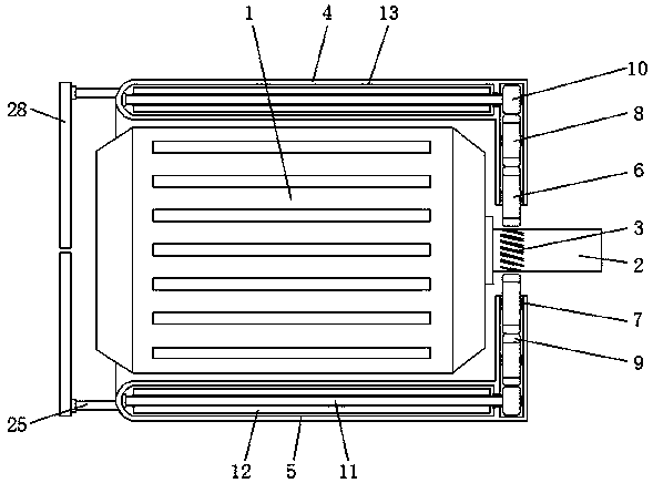
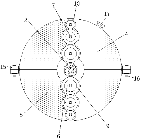
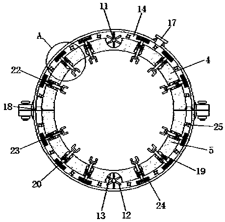
[0026] see Figure 1-6 , the present invention provides a technical solution: a water circulation heat dissipation structure driven by the power of the motor itself, including a motor body 1, a rotor 2, a connecting bolt 16 and a water injection port 17, a rotor 2 is installed on the right end of the motor body 1, and the rotor 2 Scores 3 are provided on the surface of the motor body 1, a first housing 4 and a second housing 5 are respectively installed above ...


PUM


Abstract

The invention discloses a water circulation heat dissipation structure driven by self power of a motor. The water circulation heat dissipation structure comprises a motor body, a rotor, connecting bolts and a water filling nozzle. The rotor is mounted at the right end of the motor body; the surface of the rotor is provided with nicks; a first housing and a second housing are installed above and under the motor body respectively; a connecting rod is installed at one end of a heat conduction column; a heat dissipation frame and a heat dissipation board are installed at the upper end and the lower end of the connecting rod respectively; and the heat dissipation frame and the heat dissipation board are located at the left side of the motor body. According to the water circulation heat dissipation structure driven by the self power of the motor, when the motor works, a first wheel body can be pushed to rotate by the power of the rotor; then, the first wheel body can conveniently drive related components of the heat dissipation structure to work; and finally, water circulation cooling is conveniently completed, thereby avoiding driving based on an independent power source, helping full utilization of the power and preventing power and energy waste.

Description

technical field [0001] The invention relates to the technical field of building prefabricated components, in particular to a water circulation heat dissipation structure driven by the power of a motor itself. Background technique [0002] The motor is a driving device that rotates the relevant connecting parts after being powered on. It is often used as a power source for sports machinery. Its fundamental principle is to use electromagnetic induction to convert electrical energy into mechanical energy. Therefore, in the process of motor movement , the coil and iron core inside the motor will generate high heat. Once it cannot be eliminated in time, and the temperature exceeds the maximum heat resistance of the motor, the internal winding of the motor will be damaged, which will affect the normal use of the motor. Therefore, the motor usually needs to be equipped with a corresponding Heat dissipation structure, but most of the existing motor heat dissipation structures have t...

Claims


Application Information

Patent Timeline
IPC IPC(8): H02K9/19H02K9/22H02K5/18
CPCH02K5/18H02K9/19H02K9/22
Inventor 吴淑婉
Owner JIANGSU DAZHONG ELECTRIC MOTOR
Why Eureka
Try Eureka