Wire and cable insulation injection molding device

An insulation injection molding, wire and cable technology, applied in the direction of conductor/cable insulation, cable/conductor manufacturing, circuit, etc., can solve the problems of uneven surface of cable products, poor quality, and coating can not cover the surface of the cable evenly, to achieve uniformity Injection molding work, good quality of finished product, easy to take full advantage of the effect

Pending Publication Date: 2021-01-12
永新县宏展电线电缆有限公司
View PDF0 Cites 1 Cited by
  • Summary
  • Abstract
  • Description
  • Claims
  • Application Information

AI Technical Summary

Problems solved by technology

In the traditional insulation injection molding work, the liquefied insulation injection molding raw materials are sprayed to the surface of the cable through the injection nozzl

Method used


Image

  • Wire and cable insulation injection molding device
  • Wire and cable insulation injection molding device
  • Wire and cable insulation injection molding device

Examples


Embodiment 1

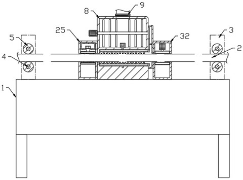
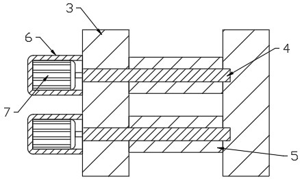
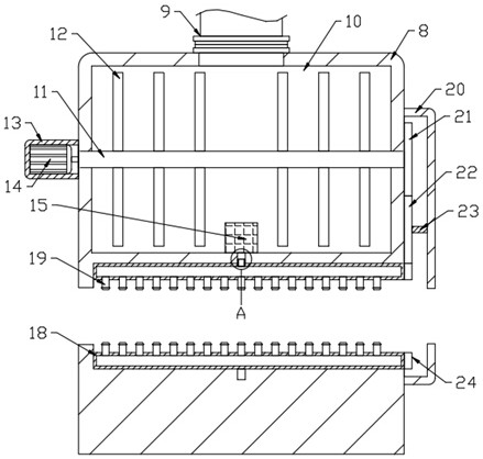
[0027] see Figure 1-7 , a wire and cable insulation injection molding device, including a workbench 1 and a cable 2 moving on the upper side of the workbench 1, the two sides of the workbench 1 are respectively provided with a column 3, and the column 3 is provided with a drive for transporting and driving the cable 2 Assemblies, the upper end of the workbench 1 is fixedly connected with the injection molding seat 8, and the injection molding seat 8 is provided with a cavity 10, and the cavity 10 is provided with a stirring assembly for stirring the injection molding raw materials, and the lower side of the injection molding seat 8 is rotatably connected with an annular injection molding box 18 The inner side of the annular injection molding box 18 is provided with a number of nozzles 19, the cavity 10 communicates with the annular injection molding box 18 through a connecting component, and the side end of the injection molding seat 8 is provided with a rotating assembly that...

Embodiment 2

[0044] This embodiment makes further improvements on the basis of Embodiment 1, and the improvements are as follows: the workbench 1 is provided with an air-drying assembly for air-drying the injection-molded cable 2, and the air-drying assembly includes an air-drying seat 32, a cooling fan 33, a connecting Pipe 34, annular blowing box 35 and orifice 37, air-drying seat 32 is fixedly connected with workbench 1, and air-drying seat 32 is provided with cooling fan 33, and the output end of cooling fan 33 is communicated with annular blowing box 35 through connecting pipe 34, and annular blowing box 35 is connected. A number of orifices 36 are provided on the inner wall of the box 35, and the cooling fan 33 provided on the air-drying seat 32 works to generate an air flow, and the air flow passes through the orifices 36 on the connecting pipe 34 and the annular blowing box 35 to air-dry the surface of the injection-molded cable 2 treatment, so that the coating on the surface of the...


PUM


Abstract

The present invention discloses a wire and cable insulation injection molding device which comprises a workbench and a cable. Stand columns are arranged at the two sides of the workbench respectively,driving assemblies are arranged on the stand columns, and an injection molding base is fixedly connected to the upper end of the workbench. A cavity, a stirring assembly, an annular injection moldingbox, a spray head and a communicating assembly are arranged in the injection molding base, a rotating assembly is arranged at the side end of the injection molding base, and an impurity removing assembly is arranged on the workbench. A rotating shaft drives a stirring column to rotate through a second motor in a second case, and the stirring column rotates to stir the raw materials in the cavity,so that the raw materials are prevented from being bonded, and the full utilization of the raw materials is facilitated. The rotation of the rotating shaft is driven by a driving gear, a transmissiongear, a transverse shaft and other components, so that the annular injection molding box rotates. The spray head on the annular injection molding box rotates in the coating spraying process, so thatthe surface of the cable is uniformly covered with coating, uniform injection molding work of the surface of the cable is realized, and the finished product quality is better.

Description

technical field [0001] The invention relates to the technical field of wire and cable processing, in particular to a wire and cable insulation injection molding device. Background technique [0002] The insulating coating can form a layer of ceramic coating with high volume resistivity on the surface of the coated object, which can withstand a strong electric field without being broken down. The coating has high mechanical strength and good chemical stability, and is resistant to aging, water, and chemical corrosion; it also has mechanical and thermal shock resistance, and the coating can work continuously at the corresponding working temperature. In the traditional insulation injection molding work, the liquefied insulation injection molding raw materials are sprayed onto the surface of the cable through the injection nozzle to pass the coating. The nozzle is fixed so that the coating cannot be evenly covered on the surface of the cable, making the surface of the finished c...

Claims


Application Information

Patent Timeline
IPC IPC(8): H01B13/16H01B13/30H01B13/00
CPCH01B13/0036H01B13/165H01B13/30
Inventor 周红亮
Owner 永新县宏展电线电缆有限公司
Why Eureka
Try Eureka