Supercharge Your Innovation With Domain-Expert AI Agents!

Detachable handle

A detachable, handle technology, applied in the field of kitchen utensils, can solve the problems of limited service life of pot handles, hidden dangers, large use safety, etc., and achieves the effect of high reliability and improved service life.

Pending Publication Date: 2020-02-11
NINGBO YINZHOU HAOSHENG PLASTIC PROD
View PDF2 Cites 0 Cited by
  • Summary
  • Abstract
  • Description
  • Claims
  • Application Information

AI Technical Summary

Problems solved by technology

[0004] The handle and clip of the detachable pot handle can be unlocked in a single-button or double-button type. The single-button type means that an unlock button is set on the handle. Press the unlock button to release the limit of the clip and the handle. It protrudes relative to the handle, but there is a greater risk of misoperation in this form, that is, during use, if the button is accidentally touched, the clip will pop out relative to the handle and the pot will fall, which is likely to cause injury or damage. Burns; on the basis of the single-button type, there has been a double-button type, that is, two unlocking buttons are set on the handle, and there is a double-button type, such as a detachable pot handle disclosed in Patent No. CN102743118B. The setting button, the two buttons cooperate with the slider in the middle to unlock, but touching any of the buttons by mistake will directly push the slider to unlock, and the clip can also pop out, which is essentially the same as the single-button structure, and there is a greater safety in use Hidden dangers, there are also some double-button types, such as a detachable pot handle disclosed in Patent No. CN205433473U. The clip is provided with a limit protrusion that is respectively matched with the two buttons. Only when the two buttons are pressed at the same time can the clip be realized. The unlocking of the clip reduces the risk of the pot falling due to a mistaken touch of one of the buttons, but the unlocking method is that the button drives the limit protrusion to elastically retract into the clip, and the limit protrusion rebounds during long-term use. It is difficult to ensure that the elasticity is constant. If the elastic force of the limit protrusion elastically returns to the limit position fails, the clip will not be able to limit the position after retracting the handle, and the service life of the pot handle will be limited.

Method used


Image

  • Detachable handle
  • Detachable handle
  • Detachable handle

Examples


Embodiment Construction

[0034] The embodiments of the present invention will be further described below with reference to the accompanying drawings.

[0035] like Figures 1 to 16 shown,

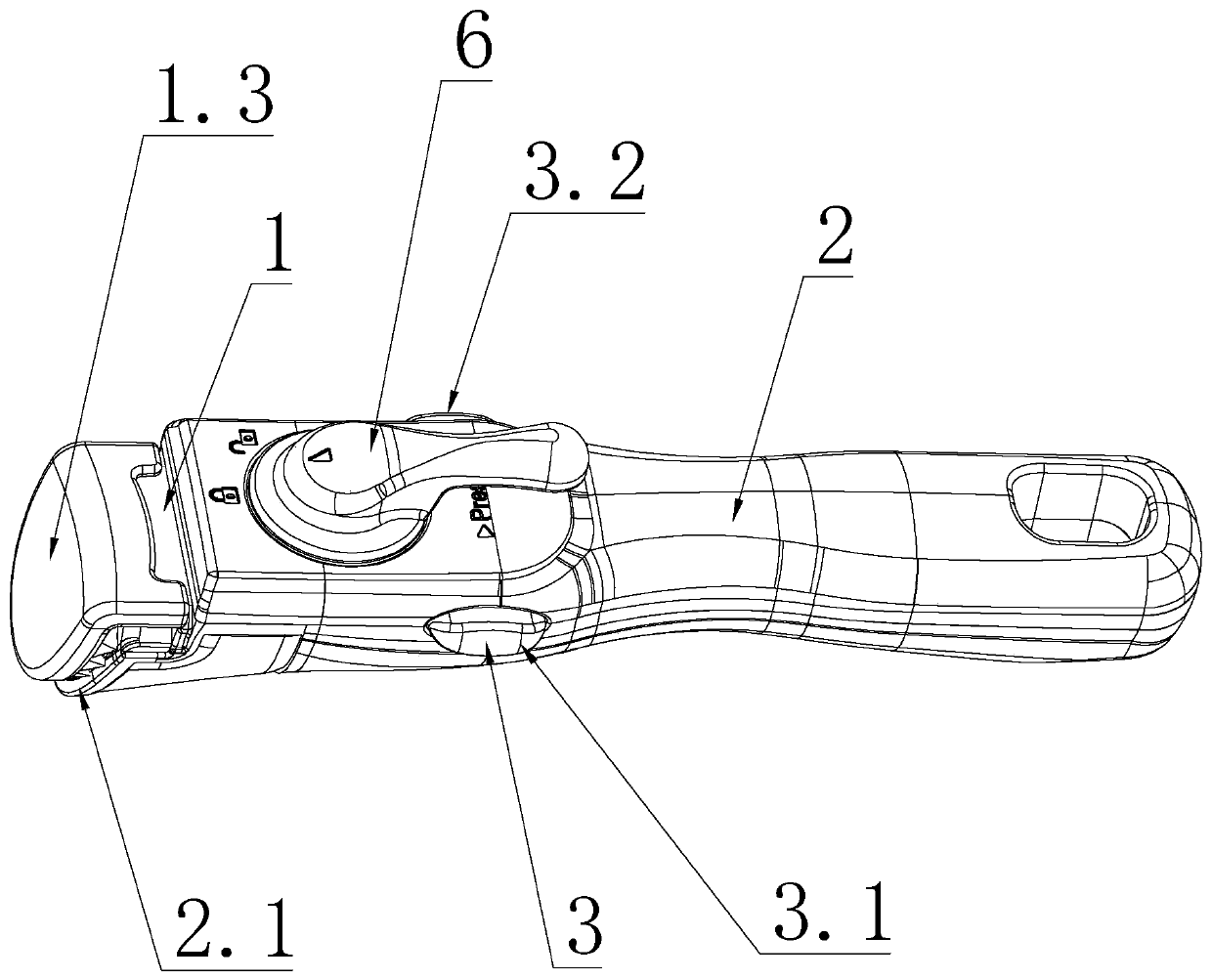
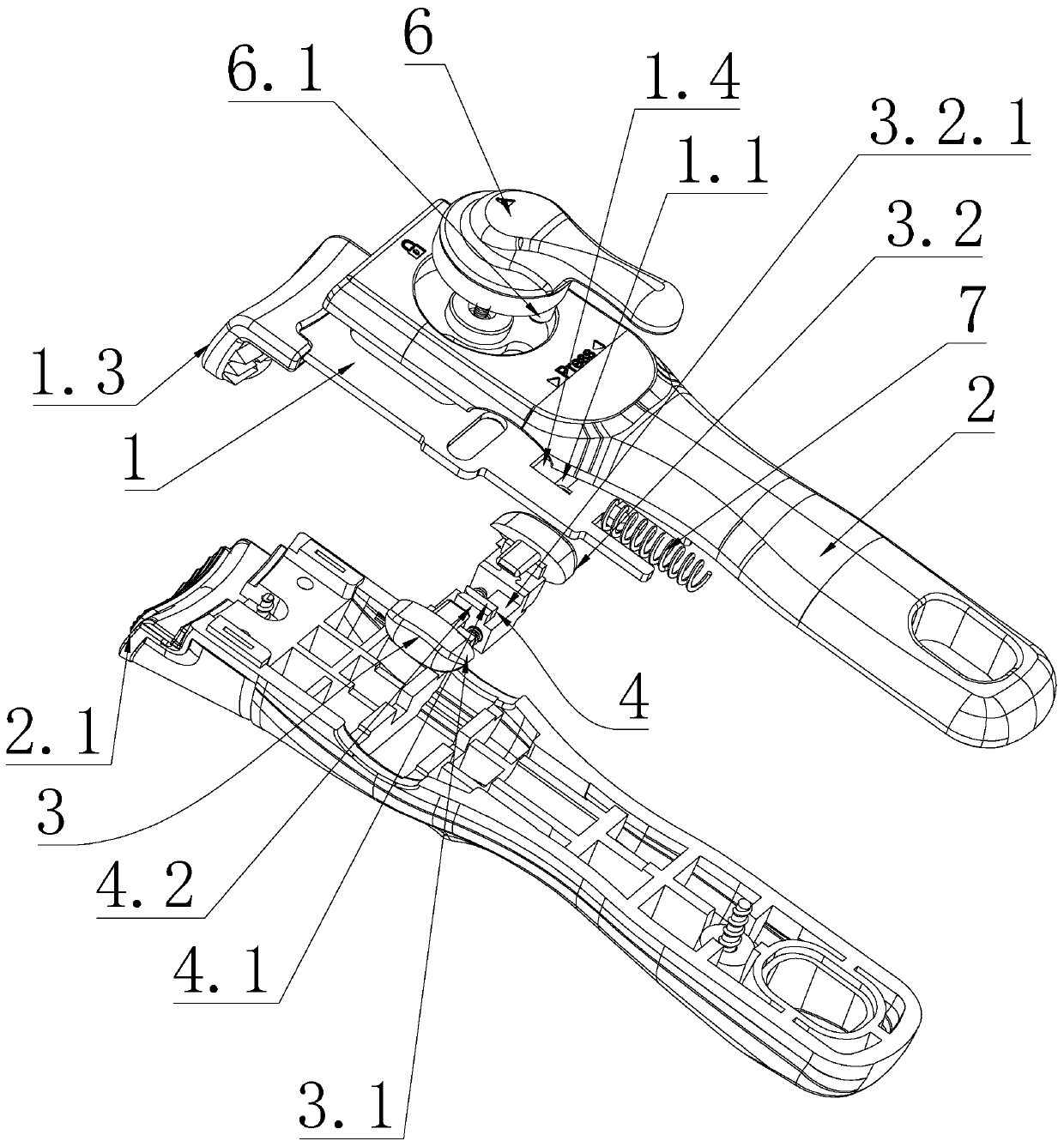
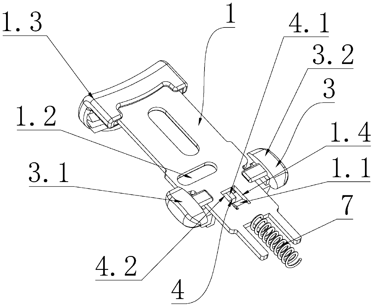
[0036] A detachable handle, comprising a handle 2, a clip 1, and a turning handle 6, the turning handle 6 is rotatably arranged on the upper part of the handle 2, a pin shaft 6.1 protrudes from the lower end of the turning handle 6, and the clip 1 moves along the vertical clip 1 The direction is provided with a drive slot 1.2 that cooperates with the pin 6.1, such as figure 1 As shown in the figure, when the handle 2 holds the cookware, the handle 6 is set towards the end of the handle 2, and the pin 6.1 is at one end of the drive slot 1.2, as shown in the figure. Figure 4 As shown in the figure, when the handle 2 is released from the cookware, the handle 6 is rotated to the side facing the handle 2. At this time, the pin 6.1 moves to the other end of the drive slot 1.2, so the operation handle 6 is rotated from...


PUM


Abstract

The invention discloses a detachable handle. The detachable handle comprises a clamping piece (1), a handle (2) and two buttons (3) arranged on two sides of the handle (2), wherein an executing piece(1.1) is arranged on the clamping piece (1), blocking pieces (4) are arranged on two buttons (3), at least one of the blocking piece (4) is propped against the executing piece (1.1) so as to limit theextending of the clamping piece (1) in relative to the handle (2); and two blocking pieces (4) are moved out and avoid the clearance (5) for the passing of the executing piece (1.5) after two buttons(3) are pressed. The invention provides a detachable handle which can unlock the clamping piece only by pressing buttons at two sides simultaneously, can unlock the nonelastic deformation between thebuttons and the clamping piece, and has good structural reliability and long service life.

Description

technical field [0001] The invention relates to the technical field of kitchen appliances, in particular to a detachable handle. Background technique [0002] In the prior art, the connection method between the cookware and the handle generally includes a detachable connection and a non-detachable connection. The non-removable connection method means that during the production and processing process, the manufacturer will directly fix the pot handle to the edge of the pot. The fixing method can be direct welding or riveting. Using this method will cause inconvenient transportation due to the large specific volume of the pot. , and if the pot handle is damaged during use, the pot handle cannot be replaced, resulting in a waste of resources and is not conducive to cleaning. [0003] There is also a detachable pot handle, including a handle and a clip, and the clip is extended or retracted relative to the handle to realize the clamping or release of the pot, which is convenien...

Claims


Application Information

Patent Timeline
Patent Type & Authority Applications(China)
IPC IPC(8): A47J45/07
CPCA47J45/071
Inventor 毛徐斌
Owner NINGBO YINZHOU HAOSHENG PLASTIC PROD
Features
  • R&D
  • Intellectual Property
  • Life Sciences
  • Materials
  • Tech Scout
  • Unparalleled Data Quality
  • Higher Quality Content
  • 60% Fewer Hallucinations
Learn More