
Electrical equipment fire extinguishing device applied to roadside high position

A technology for electrical equipment and fire extinguishing devices, which is applied in the field of electrical equipment fire extinguishing devices, can solve the problems of pedestrian danger, explosion, and increased fire degree and area of ​​insulating oil, so as to achieve the effect of convenient triggering and improving life safety

Inactive Publication Date: 2020-02-11
玉环市梓鑫机械有限公司
View PDF10 Cites 3 Cited by
  • Summary
  • Abstract
  • Description
  • Claims
  • Application Information

AI Technical Summary

Problems solved by technology

[0003] In order to improve the insulation effect, some electrical equipment erected on the high places of the utility poles on the roadside are usually filled with insulating oil inside. However, once such electrical equipment catches fire and is not extinguished in time, it will be very dangerous, and the insulating oil will aggravate the fire. The degree and area of ​​the equipment will explode in serious cases, which will bring danger to pedestrians passing by the roadside. Therefore, in the initial stage of fire of this type of equipment, timely fire fighting will greatly reduce the risk. However, because it is installed at a high place on the utility pole, That is, above the pedestrian's head, making it difficult to be detected in time

Method used


Image

  • Electrical equipment fire extinguishing device applied to roadside high position
  • Electrical equipment fire extinguishing device applied to roadside high position
  • Electrical equipment fire extinguishing device applied to roadside high position

Examples


Embodiment 1

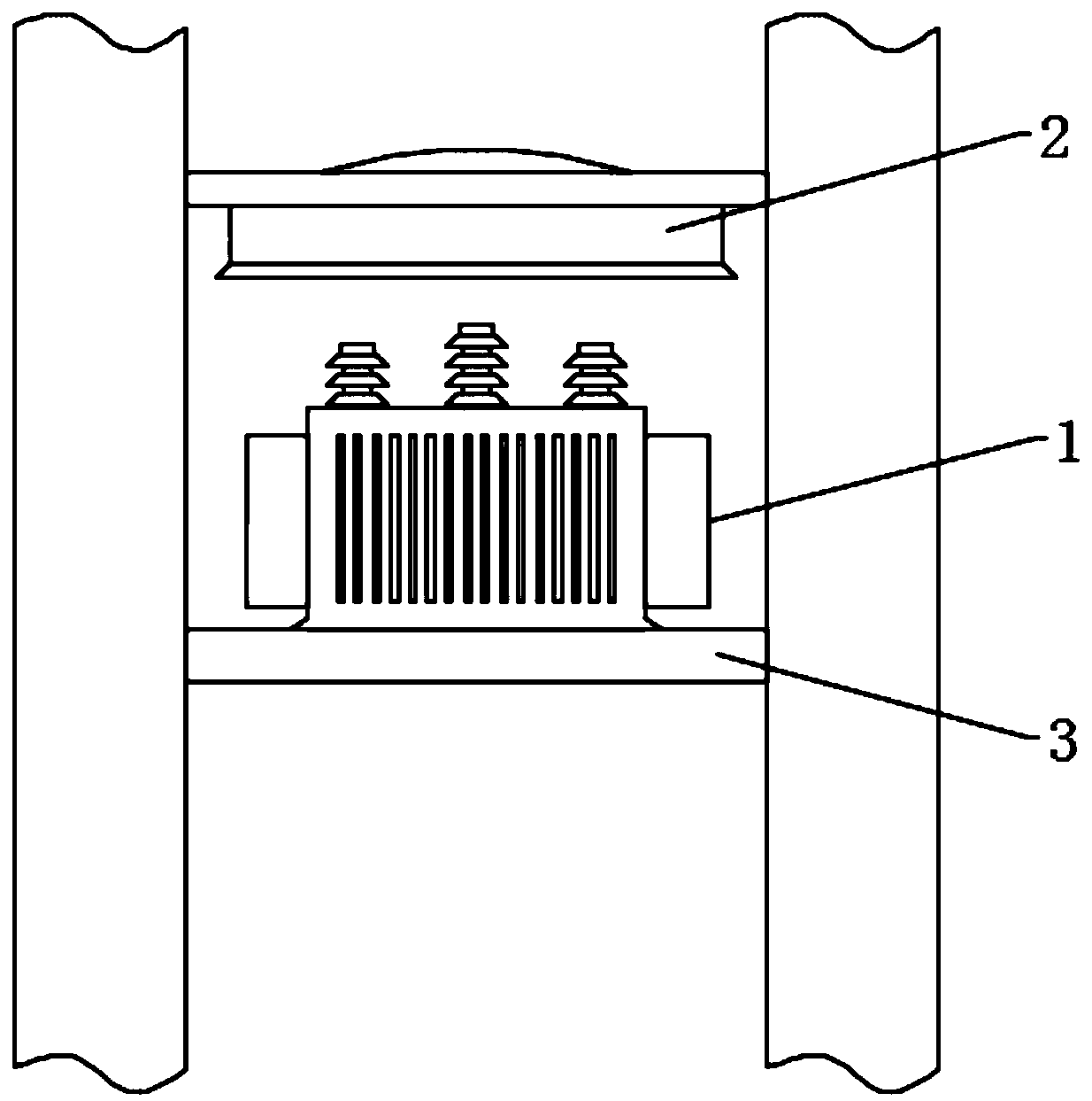
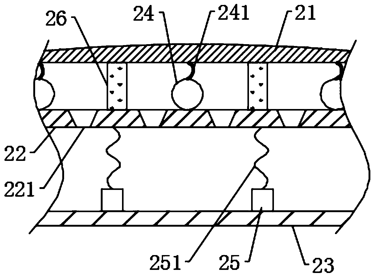
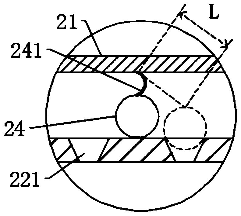
[0037] see Figure 1-2 , a fire extinguishing device for electrical equipment applied to high places on the roadside, comprising an electrical equipment body 1 arranged between a pair of utility poles, and the electrical equipment body 1 is connected to the utility pole with a mounting frame 3, the upper side of the electrical equipment body 1 A fire extinguishing device 2 is provided, and the fire extinguishing device 2 is installed between a pair of utility poles through a mounting bracket 3. The fire extinguishing device 2 includes a casing 21, an elastic partition 22 and a hard partition 23, and the hard partition 23 is connected to the lower end of the casing 21 , and the inside of the hard partition 23 and the casing 21 forms a cavity, the elastic partition 22 is fixedly connected to the inner end of the casing 21, and the elastic partition 22 separates the cavity formed by the casing 21 and the hard partition 23 into vertically distributed The second layer storage chamb...


PUM

PropertyMeasurementUnit
Thicknessaaaaaaaaaa

Abstract

The invention discloses an electrical equipment fire extinguishing device applied to the roadside high position, and belongs to the field of electrical equipment. The electrical equipment fire extinguishing device applied to the roadside high position comprises an electrical equipment body arranged between a pair of telegraph poles, and the electrical equipment body and the telegraph poles are connected with an installing frame. A fire extinguishing device is arranged at the upper side of the electrical equipment body. By arranging the fire extinguishing device at the upper side of the electrical equipment body, when the equipment is on fire, preliminary fire extinguishing is performed through fire extinguishing powder inside a first layer storage cavity, vibration is generated by a bouncyball, a digging rope, a gravity block and an extension spring, some fire extinguishing powder inside a second layer storage cavity is leaked so that the fire extinguishing effect can be enhanced, meanwhile, when fire is further spread, the fire extinguishing powder inside the second layer storage cavity is discharged for performing fire extinguishing again, and pedestrians are reminded through the bouncy ball, so that the pedestrians are evacuated out of a danger zone in time, and the life safety of the pedestrians is effectively improved.

Description

technical field [0001] The invention relates to the field of electrical equipment, and more specifically relates to a fire extinguishing device for electrical equipment applied to roadside high places. Background technique [0002] Electricity is a general term for disciplines or engineering fields such as the production, transmission, distribution, use, and electrical equipment manufacturing of electrical energy. It is a science that uses electrical energy, electrical equipment, and electrical technology to create, maintain, and improve limited spaces and environments. The conversion, utilization and research of electric energy include basic theory, applied technology, facilities and equipment, etc. Electrical engineering is one of the core disciplines in the field of modern science and technology, and it is an indispensable key discipline in the field of high-tech today. The great progress of electronic technology has promoted the arrival of the information age based on co...

Claims


Application Information

Patent Timeline
IPC IPC(8): A62C3/16
CPCA62C3/16A62C31/00A62C31/28G08B5/00G08B17/00
Inventor 刘明其他发明人请求不公开姓名
Owner 玉环市梓鑫机械有限公司
Learn More