Automatic bending machine for coil conductor

An automatic bending machine and coil conductor technology, applied in the field of bending machines, can solve problems such as difficult manual control, low bending efficiency, and poor positional accuracy control, so as to ensure the bending effect, improve the bending efficiency, The effect of reducing contact resistance

Active Publication Date: 2020-02-11
KUNSHAN LIANTAO ELECTRONICS CO LTD
View PDF7 Cites 6 Cited by
  • Summary
  • Abstract
  • Description
  • Claims
  • Application Information

AI Technical Summary

Problems solved by technology

[0003] In related technologies, the inner conductor is usually bent to the desired angle by manual visual inspection. This method has low bending efficiency, poor positional accuracy control, and uncontrollable bending force, which seriously affects the production quality of coil conductors. And production efficiency, especially when the two ends of the coil conductor need to be bent into a preset angle, it is more difficult to control manually
[0004] In related technologies, there is also a simple jig-assisted manual method to bend the inner conductor. Compared with pure manual bending, this method can improve the control accuracy of the bending position, but there are still low bending efficiency and low bending efficiency. The problem that the force cannot be controlled also affects the production quality and production efficiency of the coil conductor

Method used


Image

  • Automatic bending machine for coil conductor
  • Automatic bending machine for coil conductor
  • Automatic bending machine for coil conductor

Examples


Embodiment Construction

[0050] The technical solutions of the present invention will be clearly and completely described below in conjunction with the accompanying drawings. Apparently, the described embodiments are some of the embodiments of the present invention, but not all of them. Based on the embodiments of the present invention, all other embodiments obtained by persons of ordinary skill in the art without making creative efforts belong to the protection scope of the present invention.

[0051] In the description of the present invention, it should be noted that the terms "center", "upper", "lower", "left", "right", "vertical", "horizontal", "inner", "outer" etc. The indicated orientation or positional relationship is based on the orientation or positional relationship shown in the drawings, and is only for the convenience of describing the present invention and simplifying the description, rather than indicating or implying that the referred device or element must have a specific orientation, ...


PUM


Abstract

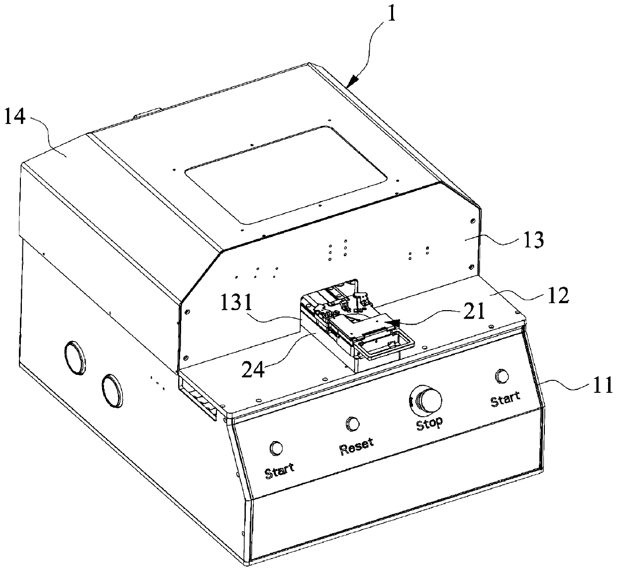
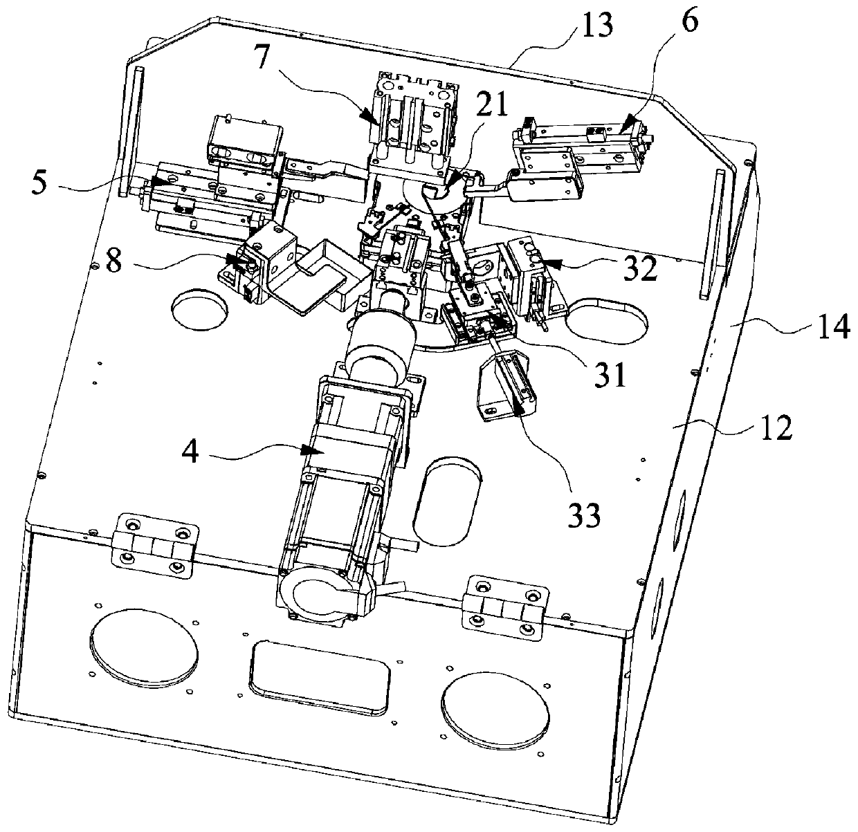
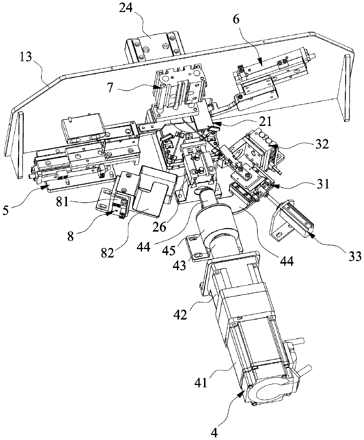
The invention relates to the technical field of bending machines, and particularly discloses an automatic bending machine for a coil conductor. The automatic bending machine for the coil conductor comprises a workbench, a carrier, a clamping jaw mechanism, a rotating mechanism and a tongue piece mechanism, wherein the carrier, the clamping jaw mechanism, the rotating mechanism and the tongue piecemechanism are arranged on the workbench; the carrier is used for fixing a coil body, the clamping jaw mechanism and the rotating mechanism are arranged at intervals, and the clamping jaw mechanism has a first position and a second position; when the clamping jaw mechanism is positioned at the first position, the tongue piece mechanism is used for abutting against the joint of the coil body and afirst conductor, and the clamping jaw mechanism is used for clamping the first conductor; and the rotating mechanism is used for driving the clamping jaw mechanism to rotate from the first position tothe second position so as to bend the joint. When the clamping jaw mechanism is positioned at the first position, the tongue piece mechanism abuts against the joint of the first conductor and the coil body, then the first conductor is clamped through the clamping jaw mechanism, and then the rotating mechanism is used for rotating, so that the joint of the first conductor and the coil body can beautomatically bent, the bending efficiency can be improved, and the labor cost can be reduced.

Description

technical field [0001] The invention relates to the technical field of bending machines, in particular to an automatic bending machine for coil conductors. Background technique [0002] The coil is a vital part of the wireless charging device. The coil is usually wound by a conductor, which includes the coil body, the outer conductor and the inner conductor. The outer conductor and the inner conductor are two parts of the conductor used to wind the coil. end. After the coil is wound, the outer conductor is tangentially matched with the outer circumference of the coil body, and the inner conductor is tangentially matched with the inner circumference of the coil body. Arrangement, which requires shaping the outer conductor and / or inner conductor of the wound coil. [0003] In related technologies, the inner conductor is usually bent to the desired angle by manual visual inspection. This method has low bending efficiency, poor positional accuracy control, and uncontrollable b...

Claims


Application Information

Patent Timeline
Patent Type & Authority Applications(China)
IPC IPC(8): B21F1/00H01F41/04
CPCB21F1/008H01F41/04
Inventor 郎咸强
Owner KUNSHAN LIANTAO ELECTRONICS CO LTD
Why Eureka
Try Eureka