
Containing frame for die steel production

A technology for placing racks and die steel, applied in the field of die steel, can solve the problem of mixing the die steel together, and achieve the effect of convenient adjustment

Inactive Publication Date: 2020-02-11
湖北三冶重工集团有限公司
View PDF0 Cites 0 Cited by
  • Summary
  • Abstract
  • Description
  • Claims
  • Application Information

AI Technical Summary

Problems solved by technology

[0004] The purpose of the present invention is to solve the shortcoming that different types of die steels will be mixed together in the prior art, and propose a placing frame for die steel production

Method used


Image

  • Containing frame for die steel production
  • Containing frame for die steel production
  • Containing frame for die steel production

Examples


Embodiment 1

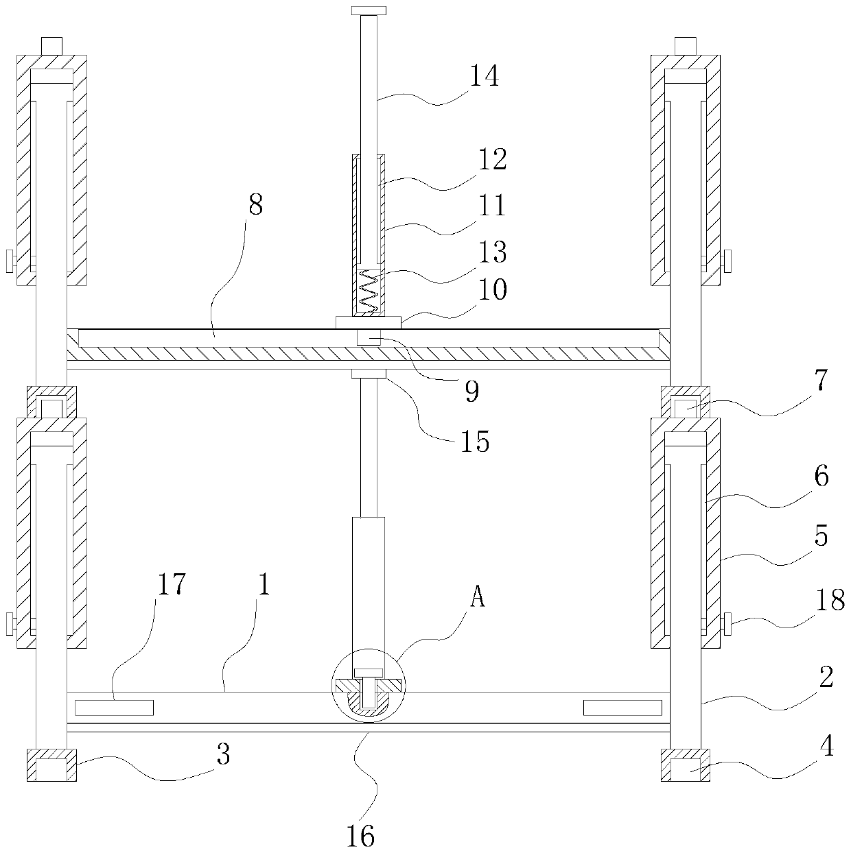
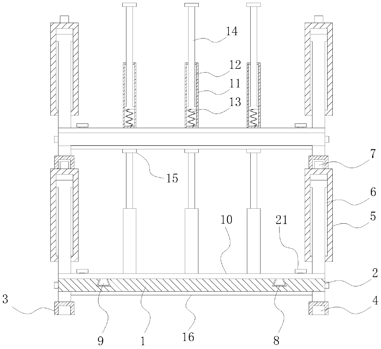
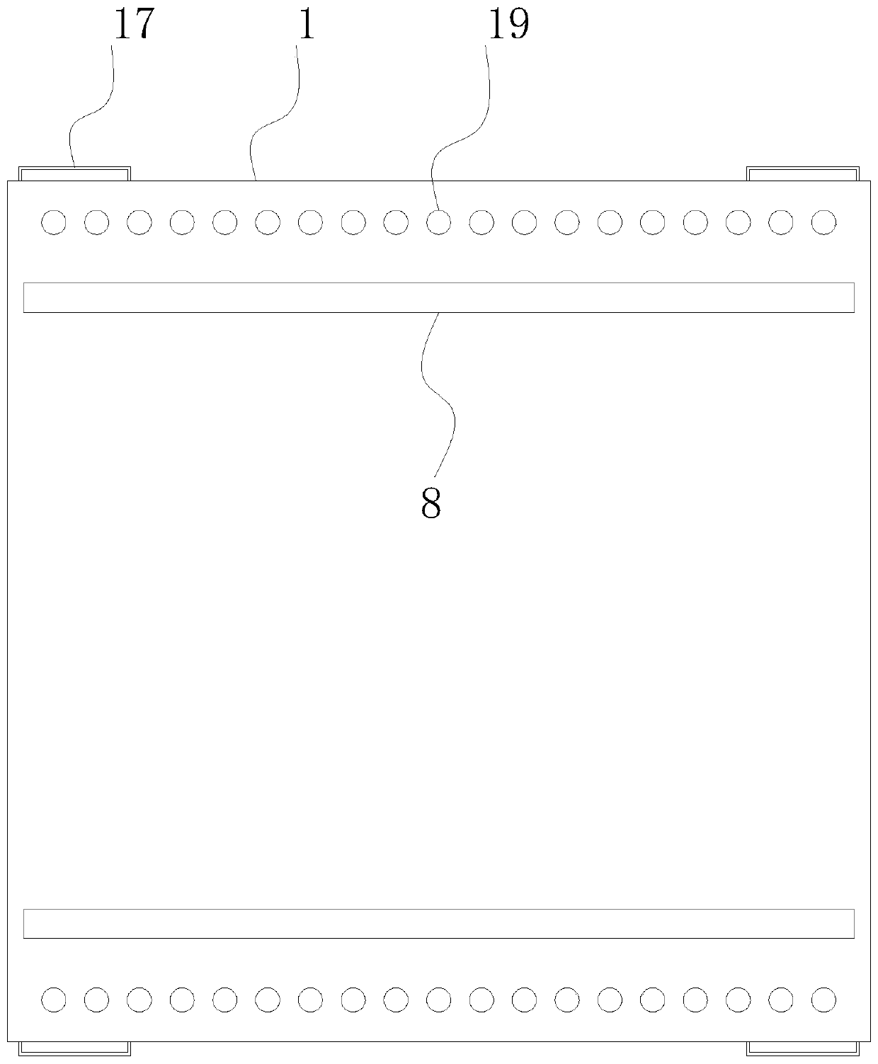
[0023] refer to Figure 1-4 , a placement frame for mold steel production, including a placement plate 1, the four corners of the placement plate 1 are welded with support rods 2, the bottom end of the support rod 2 is welded with a connecting block 3, and the middle part of the bottom end of the connecting block 3 is provided with a card slot 4. The outer surface of the support rod 2 is slidably connected with the adjustment rod 5, and the support rod 2 and the adjustment rod 5 are fixed by the first fastening screw 18, and one side of the support rod 2 is uniformly provided with the first fastening screw. Screw 18 matches the threaded hole, the middle part of the bottom end of the adjustment rod 5 is provided with the first chute 6 that matches the support rod 2, the top of the adjustment rod 5 is integrally formed with a block 7, and the top of the placement plate 1 is symmetrically provided with The second chute 8 is slidably connected with a slider 9 in the second chute 8...

Embodiment 2

[0026] refer to Figure 1-4 , as another preferred embodiment of the present invention, the difference from Embodiment 1 is that the fixing mechanism includes threaded grooves 19 evenly opened on both sides of the placement plate 1, and the two sides of the fixing plate 10 are provided with threaded holes 20, and the threaded holes 20 The internal thread is connected with a second fastening screw 21, and the second fastening screw 21 extends into the thread groove 19. The diameter of the thread groove 19 is equal to that of the threaded hole 20. Between the thread groove 19, the threaded hole 20 and the second fastening screw 21 The cooperating arrangement can further fix the fixed plate 10 and prevent the fixed plate 10 from moving, thereby preventing a large number of die steels from pushing the fixed plate 10 when they are piled up.


PUM


Abstract

The invention relates to the technical field of die steel, in particular to a containing frame for die steel production. A containing plate is included. Supporting rods are welded to the four cornersof the containing plate. Connecting blocks are welded to the bottom ends of the supporting rods. Clamping grooves are formed in the middle portions of the bottom ends of the connecting blocks. Adjusting rods are in sliding connection to the outer surfaces of the supporting rods. The middle portions of the bottom ends of the adjusting rods are provided with first sliding grooves matched with the supporting rods. Clamping blocks are integrally formed at the top ends of the adjusting rods. Second sliding grooves are symmetrically formed in the top end of the containing plate and are internally connected with sliding blocks in a sliding manner. Fixing plates are welded to the top ends of the sliding blocks. First fixing rods are evenly welded to the top ends of the fixing plates. Third slidinggrooves are formed in the middle portions of the top ends of the first fixing rods. Springs are welded to the bottom ends of the third sliding grooves, and second fixing rods are welded to one ends of the springs. By means of the containing frame, different types of die steel can be placed in a separated manner, and the situation that errors are made when a worker conducts taking is avoided.

Description

technical field [0001] The invention relates to the technical field of die steel, in particular to a placing frame for die steel production. Background technique [0002] Die steel is a type of steel used to make molds such as cold stamping dies, hot forging dies, and die-casting dies. Mold is the main processing tool for manufacturing parts in industrial sectors such as machinery manufacturing, radio instruments, motors, and electrical appliances. [0003] In the process of mold steel production and processing, the produced mold steels are basically piled up together, and after the mold steels are piled up, different types of mold steels will be mixed together, which will cause the staff to make mistakes when picking them up. Contents of the invention [0004] The object of the present invention is to solve the shortcoming that different types of die steels will be mixed together in the prior art, and propose a placing frame for die steel production. [0005] In order t...

Claims


Application Information

Patent Timeline
Patent Type & Authority Applications(China)
IPC IPC(8): B25H3/04
CPCB25H3/04
Inventor 叶兴发
Owner 湖北三冶重工集团有限公司
Learn More