
Device for automatically shearing and drawing binding iron wires

An iron wire and automatic technology, applied in the direction of conveying filamentous materials, packaging, thin material processing, etc., can solve the problems of affecting traffic, inefficiency, and tediousness, etc.

Pending Publication Date: 2020-02-11
深圳市天和双力物流自动化设备有限公司
View PDF1 Cites 4 Cited by
  • Summary
  • Abstract
  • Description
  • Claims
  • Application Information

AI Technical Summary

Problems solved by technology

[0002] In the process of industrial production and transportation, many stacks or packages are bundled with iron wires, and in order to use these stacks or recycle these packages, it is necessary to remove these bundled iron wires, but in the prior art, most of them are made by workers. Operate to remove these binding iron wires. The process of removing binding iron wires includes two parts: cutting the iron wires and pulling out the iron wires. It is necessary to switch the working tools back and forth, which is cumbersome and inefficient.
Moreover, the action of pulling out the iron wire has a large labor intensity and has certain potential safety hazards. At the same time, the removed iron wire has a loose linear structure. When it is temporarily placed next to the production line, it occupies a large area, affects traffic, and affects the cleanliness of the workshop.
[0003] Although the application number CN201020664432.X discloses an automatic wire cutting machine that can automatically remove the bundled iron wires on the stack, it is composed of a wire cutting mechanism, a wire receiving mechanism, and a combined conveying mechanism. The stacking design is relatively large, so when designing the structure, it is arranged vertically, and at the same time, a device that can be lifted up and down is installed on the wire cutting mechanism and the combined conveying mechanism, resulting in the overall structure being too large, which is only suitable for large Papermaking factories are not easy to promote, and the wire cutting mechanism and wire receiving mechanism are old-fashioned, resulting in incomplete cutting and drawing of wire, and low performance and efficiency

Method used


Image

  • Device for automatically shearing and drawing binding iron wires
  • Device for automatically shearing and drawing binding iron wires
  • Device for automatically shearing and drawing binding iron wires

Examples


Embodiment Construction

[0028] The following will clearly and completely describe the technical solutions in the embodiments of the present invention with reference to the accompanying drawings in the embodiments of the present invention. Obviously, the described embodiments are only some, not all, embodiments of the present invention. Based on the embodiments of the present invention, all other embodiments obtained by persons of ordinary skill in the art without making creative efforts belong to the protection scope of the present invention.

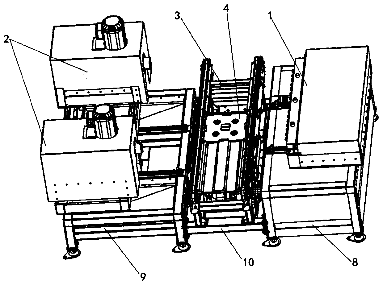
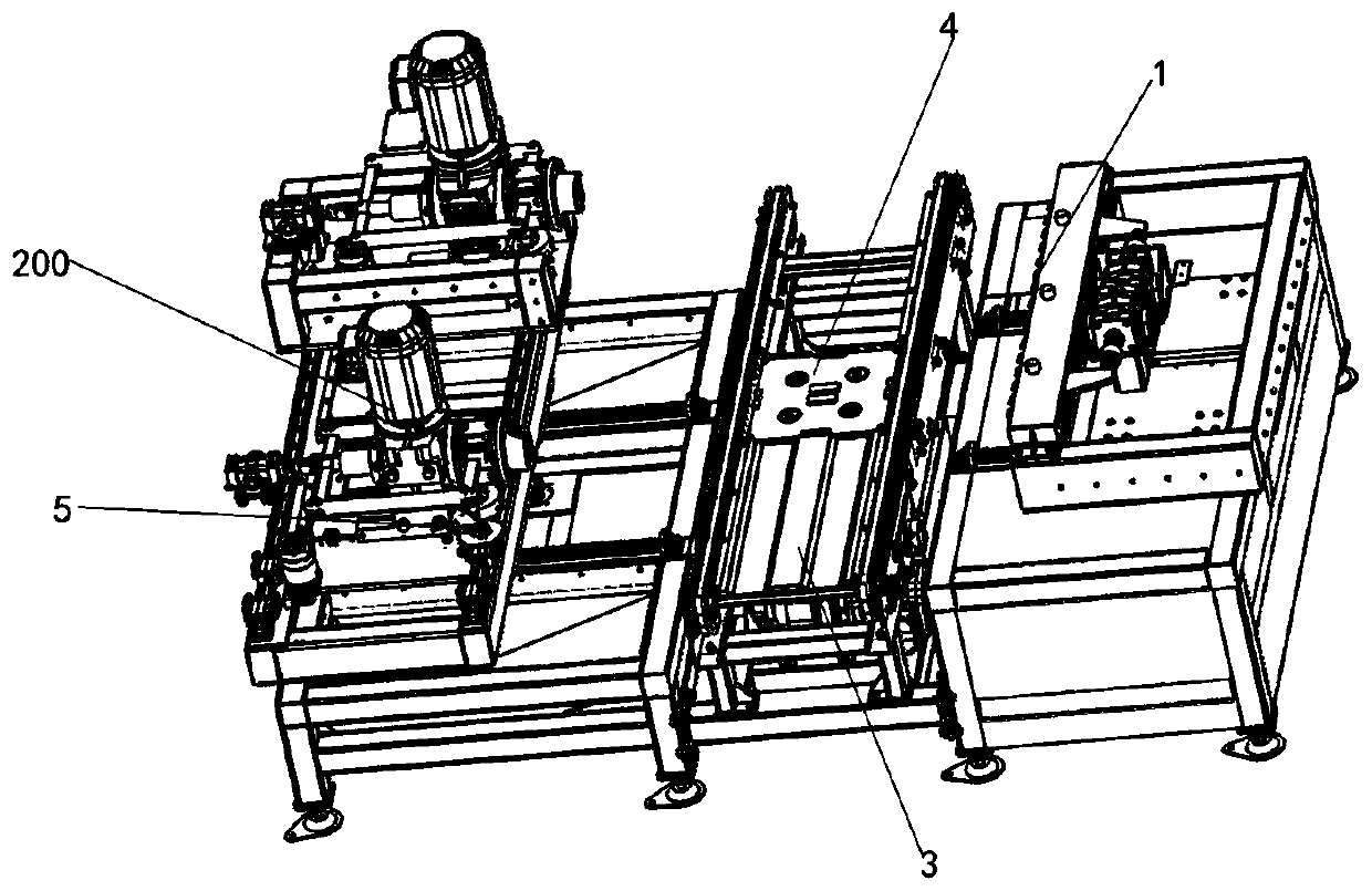
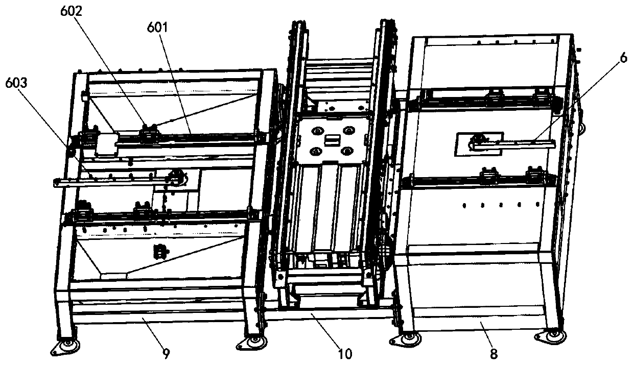
[0029] The invention provides a kind of equipment for automatically cutting and pulling away binding iron wires, including a cutting device 1, a wire drawing device 2, and a conveying line 3 arranged between the cutting device 1 and the wire drawing device 2, and the cutting device 1 is installed on the supporting frame of the cutting device 8, the wire drawing device 2 is installed on the wire drawing device support frame 9, and the conveying line 3 is install...


PUM


Abstract

The invention belongs to the technical field of mechanical equipment for packaging, and particularly relates to device for automatically shearing and drawing binding iron wires. The device for automatically shearing and drawing the binding iron wires comprises a shearing device, a wire drawing device and a conveying line arranged between the shearing device and the wire drawing device. A rotary lifting device is arranged on the conveying line. A bound package is placed on the conveying line and conveyed to the rotary lifting device. The shearing device on one side of the conveying line shearsan iron wire of the bound package. The wire drawing device on the other side of the conveying line draws the sheared iron wire from the surface of the bound package and strips the iron wire into a discharge hopper to be collected. The shearing device is movably installed on a shearing device supporting frame, and the wire drawing device is movably installed on a wire drawing device supporting frame so that the shearing device and the wire drawing device can be move away from or close to the conveying line in the horizontal direction. Through the shearing device, the wire drawing device and theconveying line, the iron wire of the bound package is sheared and drawn from the package and then is coiled to be discarded at a fixed position, so that the production efficiency is improved.

Description

technical field [0001] The invention belongs to the technical field of packaging machinery and equipment, in particular to a device for automatically cutting and pulling away binding iron wires. Background technique [0002] In the process of industrial production and transportation, many stacks or packages are bundled with iron wires, and in order to use these stacks or recycle these packages, it is necessary to remove these bundled iron wires, but in the prior art, most of them are made by workers. Operate to remove these binding iron wires. The process of removing the binding iron wires includes two parts: cutting the iron wires and pulling out the iron wires. It is necessary to switch the working tools back and forth, which is cumbersome and inefficient. And the action of pulling out the iron wire has greater labor intensity and has certain potential safety hazards. At the same time, the removed iron wire has a loose linear structure. When it is temporarily placed next t...

Claims


Application Information

Patent Timeline
IPC IPC(8): B65B61/06B65H51/00
CPCB65B61/06B65H51/00
Inventor 段小仁杨明明罗少杰刘合峰
Owner 深圳市天和双力物流自动化设备有限公司
Learn More