Pay-off device

A technology of pay-off device and connecting device, which is applied in the directions of transportation and packaging, textiles and papermaking, textile cables, etc. The effect of product quality

Pending Publication Date: 2020-02-11
南京引力工业焊接技术研究院有限公司
View PDF0 Cites 3 Cited by
  • Summary
  • Abstract
  • Description
  • Claims
  • Application Information

AI Technical Summary

Problems solved by technology

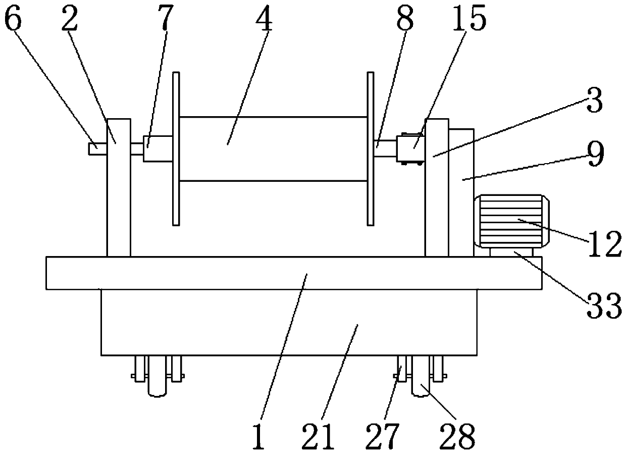
[0004] The purpose of the present invention is to provide a pay-off device, which has the advantage of being easy to replace the coil, and solves the problem that the pay-off device of the stranding machine is mostly a fixed structure, which limits the range of installation and use of the I-shaped wheel, and must be used in different pay-off devices. The problem of using the matching I-shaped wheel

Method used


Image

  • Pay-off device
  • Pay-off device
  • Pay-off device

Examples


Embodiment Construction

[0020] The following will clearly and completely describe the technical solutions in the embodiments of the present invention with reference to the accompanying drawings in the embodiments of the present invention. Obviously, the described embodiments are only some, not all, embodiments of the present invention. Based on the embodiments of the present invention, all other embodiments obtained by persons of ordinary skill in the art without making creative efforts belong to the protection scope of the present invention.

[0021] In the description of the invention, it should be noted that the terms "upper", "lower", "inner", "outer", "front end", "rear end", "both ends", "one end", "another end" etc. The indicated orientation or positional relationship is based on the orientation or positional relationship shown in the drawings, and is only for the convenience of describing the present invention and simplifying the description, rather than indicating or implying that the referre...


PUM


Abstract

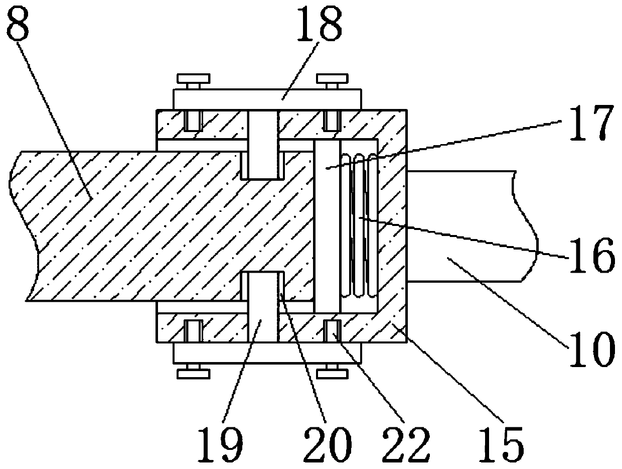
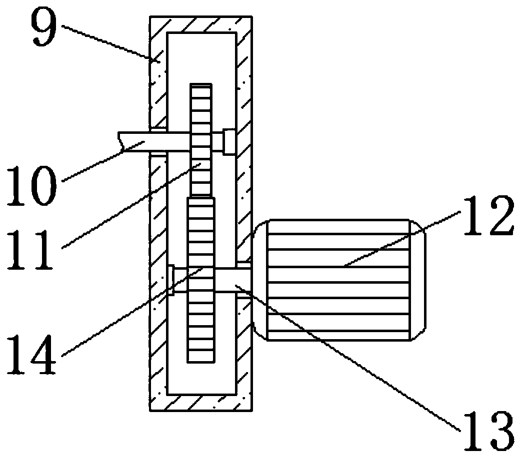
The invention discloses a pay-off device. The device comprises a fixed frame, the left side of the top of the fixed frame is fixedly connected with a first supporting frame, a second supporting frameis fixedly connected to the right side of the top of the fixed frame, a pay-off roller is movably connected between the first supporting frame and the second supporting frame, and a bearing is fixedlyconnected in an inner cavity of the first supporting frame. Through cooperation use of the fixed frame, the first supporting frame, the second supporting frame, a pay-off roller, a bearing, a fixed shaft, a thread sleeve, a connecting device, a shell, a transmission rod, a driven gear, a first motor, a rotating shaft, a driving gear, a casing pipe, a spring, a base plate, fixed blocks, clamping blocks, clamping grooves and a box body, a pay-off device of a traditional stranding machine can be improved, on the basis of keeping original self rotation, the adaptation range of a spool can be expanded, and the aims of being convenient to mount and dismount, reducing person carrying, improving work efficiency and improving product quality are achieved.

Description

technical field [0001] The invention relates to the technical field of twisting machines, in particular to a wire pay-off device. Background technique [0002] The stranding machine is a machine used to twist a number of metal wires into strands according to a certain twist distance and twist direction. According to the structure type of the body, the stranding machine has several types such as basket type, tubular type and tubeless type. The stranding machine is composed of one or several sections of barrel body. The line-carrying I-shaped wheels are arranged in a line along the center of the body. The traction cooperates to make the steel wire produce helical winding and linear movement of the strands, forming strands with a certain lay length, thus completing the basic twisting action of the strands. Compared with the basket machine, the twisting principle is the same, but the structure However, it has been significantly improved. The tubular stranding machine is small i...

Claims


Application Information

Patent Timeline
Patent Type & Authority Applications(China)
IPC IPC(8): B65H49/30B65H49/34D07B3/00
CPCB65H49/30B65H49/34B65H2701/36D07B3/00
Inventor 时振齐兴佳粟正义
Owner 南京引力工业焊接技术研究院有限公司
Why Eureka
Try Eureka